Table of Contents

Related Manuals for HELI gleen G Series


Summary of Contents for HELI gleen G Series
- Page 2 FOREWORD Battery counterbalanced forklift truck is designed on the base of advantages of some trucks made by domestic and foreign manufacturers and developed in introduced technology from abroad. These trucks are all suited for handling and stacking goods in stations, ports, goods yards and warehouses and used widely in food processing, light and textile, mining industries and other factories, with some of attachments fitted, the trucks can be applied more and more.
-
Page 3: Table Of Contents
CONTENTS I. Safety Rules for Opeartion and Daily Maintenance of Forklift Truck ....... 1 II. Main Specifications of Forklift Truck ............... 6 III. Construction, Priciple, Adjustment and Maintenance of Forklift Truck ....10 1. Transmission System ..................10 2. Brake System ....................14 3. -
Page 4: Safety Rules For Opeartion And Daily Maintenance Of Forklift Truck
Ι. Safety Rules for Operation and Daily Maintenance of Forklift Truck It is important that driver and manager for forklift trucks remember the principle of the “first safety” and ensure the safety operation as the description in 《OPERATION AND SERVICE MANUAL》&《OPERATION MANUAL》. 1. - Page 5 (1) Only trained and authorized operator shall be permitted to operate the truck. (2) Wear all the safety guards, such as shoes, helmet, clothing and gloves while operating the truck. (3) Check all the control and warning devices before starting the truck. If any damages or defects are found, operate it after repairing.
- Page 6 unloading. (14) Be careful and slowly driving over a dockboard or bridge-plate. (15) Shut down the truck and don‟t stay on the truck when checking battery or fuel lever. (16) The unloaded forklift truck with attachments should be operated as a loaded truck.
- Page 7 (2) Oil used for forklift trucks Recommended Name Brand and temperature of using brand L-HM32 L-HV32 low Sticky grade wearable temp. wearable Hydraulic oil Chang cheng hydraulic oil hydraulic oil ≥-20 (cold Temp. of ≥-5 using (℃) region) Chong qing Brake fluid 4604 compound brake fluid GB 12981 HZY4...
- Page 8 (3) The table of lubrication system...
-
Page 9: Main Specifications Of Forklift Truck
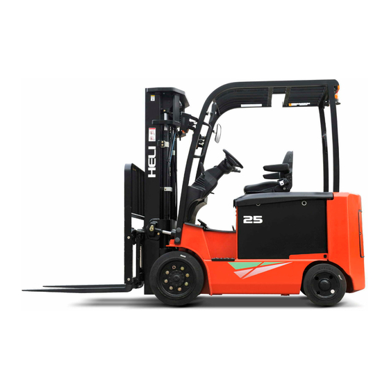
Ⅱ. Main Specifications of Forklift Truck Enternal view of forklift trucks... - Page 10 Main Specifications Model CPD20 CPD25 Unit Type GA2C/GA2CP GA2C/GA2CP Rated capacity lbs/kg 4000/2000 5000/2500 Load center in/mm 24/500 Lifting height in/mm 4700/185 Free lift height in/mm 44/1117 Mast tilting angle deg. (front/rear) (K/T) Fork size (L*S*E) 1070×122×40 Wheel base F 1340 Front and rear tread (B1/B2) 890/920...
- Page 11 Main Specifications Model CPD25 CPD30 CPD30 单位 Type GB2C/GB2CP GA2C/GA2CP GA2C/GAC2P Rated capacity lbs/kg 5500/2500 6000/3000 6000/3000 Load center in/mm 24/600 24/500 24/500 Lifting height in/mm 4700/185 4700/185 Free lift height in/mm 44/1117 39/990 Mast tilting angle (front/rear) deg. (K/T) Fork size (L*S*E) 1070×122×40 1070×125×45...
- Page 12 Size and weight of the main parts that can be disassembled Model CPD20 CPD25 CPD25 CPD30 CPD32 Unit Item GA2C/GA2CP GA2C/GA2CP GB2C/GB2CP GA2C/GA2CP GA2C/GA2CP Max. overall 380×1072×1005 390×1072×1005 390×1072×1005 390×1072×990 408×1072×990 size Counterweight 1210 1310 Weight Max. overall 1522×1045×1645 1522×1045×1645 1050×1414×1551 1100×1457×1515 1100×1457×1515...
-
Page 13: Construction, Priciple, Adjustment And Maintenance Of Forklift Truck
Ⅲ. Construction, Principle, Adjustment and Maintenance of Forklift Trucks 1. Transmission System 1.1 General description The transmission system consists of differential assembly and gearbox & axle assembly. With direct connection of the drive gear and the drive motor, the travel speed of the truck can be changed with the speed of the motor, and the travel direction can be changed with the rotation direction of the motor. - Page 14 8. Bolt 1.3 Gearbox & axle assembly The gearbox & axle assembly mainly consists of the housing, hub the wheels. It is installed in the front of the frame. The housing is an fission cast. The tyre with the rim is fixed to the hub with bolts and nuts.
- Page 15 Fig. 1-2 Gearbox & axle assembly (3) Spindle head assembly of the axle housing Ⅰ (1) Differential assembly (2) Main housing of the reducer casing (4) Connecting plate (5) Brake assembly (R) (6) Brake drum hub assembly (7) Half-shaft Ⅰ (8) Oil seal AE2483E0 (9) Bolt( for 2-3t brake) (10) Washer 20...
- Page 16 1.4 Assembly of wheel hub (1) Fill the chamber of wheel hub with lubricating grease about 100cc, and then fit the hub on the housing. (See Fig. 1-4) (2) Tighten the hub nut with a torque of Adjust nut 1kg.m, then loosen it for 1/2 turn. Locking plate Locking nut Fig.
-
Page 17: Brake System
2. Brake System 2.1 General description The brake system is the front two-wheel braking type consisting of brake pedal, master cylinder and wheel brakes. 2.1.1 Brake pedal The structure of the brake pedal is shown in Fig. 2-1. The brake pedal is mounted on the transmission through bracket. - Page 18 rod pushes the piston forward. The brake fluid in the cylinder flows back to the reserve tank through the return port until the primary cup blocks up the return port. After the primary cup passes through the return port, the brake fluid in the cylinder is pressurized and opens the check valve, flowing through the brake pipeline to the sub cylinder.
- Page 19 2.1.3 Wheel brake The wheel brake is of double brake shoe type which is fitted to the each end of the gearbox & axle assembly. The wheel brake is made up of two brake shoe, sub cylinder and adjuster. The brake shoe, one end of it being connected to the anchor pin and the other to the adjuster, is stressed on backing plate by the spring and spring pull rod.
- Page 20 (2) Parking brake The parking brake is built in the wheel brake which is made up of push rod and pull rod. The pull rod is mounted to the primary shoe side by pin. The move of the pull rod is transmitted to the secondary shoe side through push rod.
- Page 21 travel. ▲Operation of the clearance self-adjuster When brake during travelling backward, secondary brake shoe contact with main brake shoe and rotate together. Then the pulling rod turns right with point A as pivot and thus B point is raised up. See figure 2-6. When brake is released, the pulling rod turn left under the spring action and thus B point lowers.
- Page 22 Fig. 2-8 Wheel brake (1) Braking cable ass‟y (2) Washer 8 (3) Bolt M8×20 (4) Ratchet pawl (5) Pin roll (6) Torsional spring (7) Parking push rod (8) Spring (9) Rear brake shoe with friction plate (10) Spring pull rod (11) Return spring for brake shoe (12) Guide pad (13) Guide plate...
- Page 23 Brake force adjustment: When you turns the adjuster clockwise, the force increases, otherwise, when you turns the adjuster counter clockwise, the force decreases. (See Fig. 2-9) Pull force: 20 to 30kg. Note: Adjuster is inside the cover. Cover need to be disassembled before adjusting.
- Page 24 (2) Remove two shoes return springs. (See Fig.2-11) Fig. 2-11 (3) Remove hold-down springs on primary brake shoe. (See Fig. 2-12) Fig. 2-12 (4) Remove the primary and secondary shoes. At the same time, remove adjuster spring. (See Fig. 2-13) Fig.
- Page 25 (5) Remove the brake line from the wheel cylinder. Remove wheel cylinder mounting bolts and detach the wheel cylinder from the backing plate. (See Fig. 2-14) Fig. 2-14 (6) Remove the E-retainer for securing the parking brake cable to the backing plate. Remove the backing plate mounting bolts and detach the backing plate from the axle.
- Page 26 (1) Check the operating cylinder inner surface and the piston periphery surface for rusting. Then, measure the clearance between the piston and cylinder. (See Fig.2-17) Fig. 2-17 Standard: 0.03-0.10mm Maximum clearance: 0.15mm (2) Visually check the piston cup for damage or deformation. If unsatisfactory, replace with new one.
- Page 27 2.2.3 Wheel brake reassembly (1) Apply brake fluid to the piston and the piston cup, and reinstall the spring, cup, the piston and the dust cover in this order. (2) Install the operating cylinder on the backing plate. (3) Install the backing plate on the front axle. (4) Apply heat-resisting grease on the points indicated in Fig.
- Page 28 (8) Install the shoe guide plate on the anchor pin, and install the shoe return spring. (See Fig. 2-22) Fig. 2-22 (9) Install the adjuster, adjuster spring, push rod and its return spring. Pay attention to the following points: a) Adjuster thread direction and its mounting direction. b) Adjuster spring direction.
- Page 29 (11) Measure the inner diameter of drum and the outer diameter of brake shoe. Adjust the adjuster to obtain the 1mm difference needed between the drum inner diameter and the friction piece outer diameter. (See Fig. 2-24) Fig. 2-24 2.2.4 Operation test to clearance-self-adjuster (1) Make the brake shoe diameter approach the specified mounting size, and pull the adjusting level with your finger along the arrow marks to turn the adjuster gear.
- Page 30 Fig. 2-25 2.2.5 Brake pedal adjustment (1) Make the push rod short. (2) Adjust the stopper bolt and the height of the pedal. (See Fig. 2-26) (3) Press the brake pedal. Pull the push rod out until its front end comes into contact with the master cylinder piston.
- Page 31 ▲ Brake switch adjustment a) After you adjust the height of the brake pedal, loose the lock nut of the brake switch. b) Pull the plug out to let the lead separate. c) Turn the switch to make the clearance about 1mm. d) Make sure that when you press the brake pedal the brake lamp light at the same time.
-
Page 32: Steering System
3. Steering system 3.1 General Description The function of steering system of forklift is to change the driving direction of the forklift or keep the forklift in straight line driving. The performance of steering system directly concerns with the driving safety, operation efficiency of forklifts and labor intensity of drivers. - Page 33 The difference between fully hydraulic and hydraulic power steering gears is the first substitutes the mechanical elements such as steering gear and longitudinal tie etc and has high pressure oil pipe connecting fully hydraulic steering gear with oil cylinder. The pressure-gradient control valve mounted in the loop of load- sensing and fully hydraulic steering system can ensure distribution of flow to steering system first and sufficient oil supply at any working conditions.
- Page 34 (2) Steering gear G-series 2.0-3.2t forklift with cushion tire adopts cycloid rotary valve type fully hydraulic steering gear and it is a closed-type dynamic load steering gear. Refer to hydraulic system for details). (3) Transmission gear for steering The mechanism that deflects the right and left wheels according to a certain relation through oil cylinder and steering mechanism with power output by steering gear is called transmission gear and it is realized though horizontal style oil cylinder steering axle assemblies.
- Page 35 Figure 3-2 (1) steering knuckle main pin (2) needle bearing (3) thrust bearing (4) oil seal (5) steering wheel assembly (6) tapered roller bearing (7) washer (8) lock nut (9)hub cover (10)tapered roller bearing (11)lock pin (12) steering knuckle (13) seal ring (14) damping block (15) dust proof cover (16) steering cylinder...
- Page 36 Figure 3-3 Steering knuckle (1) Thrust bearing (2) knuckle (3) dust-proof cover (4) steering knuckle pin (5) needle bearing (6) shock absorber (2) Steering cylinder (2) Steering cylinder The steering cylinder is of double-action piston type. Both ends of the piston rod are connected with steering knuckles through connection rod.
- Page 37 Figure 3-4 Steering cylinder (1) cylinder bore (2) supporting ring (3) cylinder cover (4) O ring (5) O ring (6) O ring (7) U ring (8) Dust proof ring (9) snap ring (10) piston rod assembly (3) Rear wheel assembly Refer to figure 3-5 for rear wheel assembly.
- Page 38 3.5 Adjustment and Maintenance 3.5.1 Rear wheel bearig pre-load adjustment (1) As shown in Fig. 3-5, fill up the chamber formed by wheel hubs, wheel hub bearings and wheel hub covers with lubricating grease. Coat the lips of the oil seals with lubricating grease.
- Page 39 above-mentioned, screw out the castle nut for 1/6 turn and measure the torque value then. (8) When the torque value measured is up to the specified one, lock the castle nut with a cotter pin. 3.5.2 Maintenance and service of steering system (1) The steering king pin needs to be checked every 40 hours and grease be replenished to the bent neck type grease fittings of king pin every 300 hours, piston rod and link rod of steering oil cylinder, rotation connection parts of right and left knuckle arm need to be...
- Page 40 3.6.2 Steering system troubleshooting Table 3-2 Problem Analyses of trouble Remedies Fail to turn Pump damaged or breaking down. Replace hand-wheel Hose or joint damaged or pipeline blocked. Clean or replace The pressure of the safety valve is too low. Adjust the pressure Air in steering oil circuit.
-
Page 41: Electric System
It is mainly made up of smart meter, control system, traction motor, pump motor, battery, control switch, lightings, harness and so on. 4.1.2 Main configuration HELI truck Traction Pump Main... - Page 42 Note: manufacurer keeps the right of prodct imporving, if the real product is not agree with the manual, please consult with the manufacurer.
- Page 43 4.1.4 Electric system priciple diagram Figure 4-1 Electric system priciple diagram (CPD20-32- GA2C(P))
- Page 44 Turn on the key switch. When the instrument gets power “HELI AC SYSTEM” is displayed on the LED screen. After system self-testing, battery capacity, truck speed, the default setting (economic mode) and traction hours will be indicated on the main page, as shown in Fig.
- Page 45 Fig. 4-9 Display of the ZAPI instrument when power on (fault-free) b) Battery capacity display: There are 20 grids on the battery capacity indicator. After the truck is powered, the indicator is fully lit (20 grids) if the battery is fully charged.
- Page 46 4.3 Controller 4.3.1 General description ZAPI AC2 motor controller which has high frequency MOS pipe technology, superior speed adjusting, good safety, flexibility and top-ranking protection is assembled on the truck. Controller assembly includes motor controller, contactor, relay, fuse, OPS alarming, back buzzer, cooling fan and relative harness.
- Page 47 and the manufacturer will be informed in time for after sales service in case of fault. Please do not open it for maintenance without authorization of manufacturing. The users will be responsible for the personal and property losses caused by maintenance at their own will.
- Page 48 Voltage Ceil number Note: imported battery is optional. 4.4.2 Use of battery The correct use and daily maintenance of lead-acid battery have a great influence on the performance and service life of battery, therefore, the users must make maintenance and service by contrast with the actual condition and according to the maintenance instruction provided by manufacturer.
- Page 49 seriously affect the service life and performance of battery. (8) Battery after use should be charged within 24 hours. Failure to charge the battery timely, undercharge, excessive discharge or unused for a long time without additional charging will vulcanize polar plate of battery and result in performance degradation and use difficulty when serious.
- Page 50 Notice: (1) The rated voltage of traction battery is not the safe voltage and there is electric shock injury danger if touched, so take safety precautions. (2) Traction battery is lead-acid battery and electrolyte is dilute sulphuric acid. So when the battery is tested, fed and adjusted etc, wear safety device to avoid accident.
- Page 51 creepage. range. 1) Low battery voltage or 1) Curve pole plate; 1) Replace the plate. close to zero indeed when expanded reactive matter; 2) Clean the precipitate charging. desquamated reactive and conductor. 2) Few or no air bubble at matter. 3) Replace the plate.
- Page 52 damage or condition affecting the safety, contact with ZAPI dealer. Notice: After chopper is installed, raise the wheel of vehicle (off the ground) for test. In this way, there will be no danger even connection is wrong. After electric lock switch is off, there is a certain voltage left in filter capacitor within a period of time.
- Page 53 b. Turn on the key switch and adjust the traction controller parameter first. c. Press the “*” button twice continually on smart meter and the following on the meter is displayed: d. enter password:55555( press 5 for 5 times) and the follwing on the meter is displayed: e.
- Page 54 k. Press “*” on the meter once and the following is displayed: l. Press “1” or “2” until the following is displayed: m. According to the mounted battery voltage, press “3” or “4” to adjust to proper voltage. For example, when adjusting form 36V to 48V, press “3” or “4” until the following is displayed: n.
- Page 55 t. Use the multimeter to measure the voltage between positive pole and negative pole of the controller. Press “3” or “4” to calibrate voltage until the parameter is more or less the same as the measured value. For example the measured value is 37.5V, press “3” or “4”...
- Page 56 c) Press 1 or 2 until the following is displayed: d) Press * key on SMART meter once and the following on the meter is displayed: e) Press * key on SMART meter once and the following on the meter is displayed: f) Choose the forward switch and step the accelerator to the max.
- Page 57 i) Release the accelerator and the direction switch returns to the neutral position. The following is displayed on the meter: j) Press the 5 on the SMART meter once and the following is displayed on the meter. k) Press * key on the SMART meter once and the following on the meter is displayed: l) Turn off the key switch.
- Page 58 c) Press 1 or 2 until the following is displayed: d) Press * key on the SMART meter once and the following on the meter is displayed: e) Press * key on the SMART meter once and the following on the meter is displayed: f) Operate the lifting rod to the max.
- Page 59 j) Turn off the key switch. C. Steering angle potentiometer sampling method a) Turn on the key switch and enter the traction controller. See the following figure. b) Press the 1 or 3 on the meter at the same time and the following is displayed on the meter: c) Press the 1 twice and the following is displayed on the meter.
- Page 60 through operating steering wheel. At this time, the parameter changes continually. When the steering wheel is in neutral position, the parameter is decided. if 5.2V is assumed to the value, the following is displayed: g) Press the * on the meter twice and 5 once. The following is displayed on the meter.
- Page 61 m) Press the * key on the meter once and the following is displayed on the meter. n) Press the * key on the meter once and the following is displayed on the meter. o) Press 1 or 2 until the following is displayed on the meter. p) Press the * on the meter once.
- Page 62 s) Turn off the key switch. 4.7 Fault code display----ZAPI control system When an alarm condition occurs, Smart Display gives the information showing the alarm code in the first row and the module number in the second row. For example ,the information: means that the alarm 60 occurred in the AC module N.5(pump).
- Page 63 4. Check if the calibrated parameter of the controller voltage is the same as the actual voltage. 5. Electric circuit of the over voltage protecting hardware has fault, change controller. VMN LOW The test is carried out during initial diagnosis and in standby.
- Page 64 If the “battery check” option is ON, a battery discharge algorithm BATTERY is carried out. When the charge level is 10%, this alarm is signalled and the current is reduced to the half of the programmed level. When the key is switched ON, the μP checks that the MC coil DRIVER SHORTED drive is not...
- Page 65 both are electric and the mechanical encoder functionality. Also the electromagnetic noise on the sensor bearing can be a cause for the alarm. It all above are all right, change the controller. Please note that manual operation can cause the fault also, at this time, shut off the power and start again.
- Page 66 B) failure of the microswitch C) incorrect operation of the operator D) if the detect persist, replace the logic WAITING FOR The controller receives from a remote module via CAN BUS the information that it isn‟t possible to close the LC (the module isn‟t NODE ready locked in an alarm state).Verify the other modules to determinate in which of them there is the problem.
- Page 67 Possible causes: VMN HIGH A) Problem with the motor connections or the motor power circuit; check if the 3 phase are correctly connected; check if there‟s a dispersion of the motor towards ground; B) Invert failure, replace it The controller checks if the LC contact is closed when the CONTACTOR CLOSED coil isn‟t driven, trying to discharge the capacitor bank.
- Page 68 The fault occurs when the motor temperature digit switch MOTOR TEMPERAT. opens or analog signal exceeds cut-off value. If the fault still exists when the motor is cold, check the electric circuit or motor temperature parameter. If all are ok, change the logic card.
- Page 69 Check the encoder mechanical function and electric circuit. electromagnetic noise on sensor bearing causes alarm. If all are right, change the controller. The alarm sounds up if lifting potentiometer cable PEDAL WIRE KO connecting is not correct (NPOT or PPOT is open, or the service power of the lifting potentiometer is not correct.
-
Page 70: Hydraulic System
4.7.3 Instrument part (node 16) Error Analysis Description code The memory storing adjusting parameter has fault. when the fault EEPROM KO occurs, machine stops working automatically. If the fault still exists after turning off the switch and reconnects, change the controller. - Page 71 to cylinders by the control valve. 5.1.1 Oil pump The main parts of the gear oil pump for forklift are a pair of external gears mutually meshed and their working principle is as shown in Fig. 5-1. Figure 5-1 Gear pump working priciple diagram (1) oil suction cavity (2) Pressure oil cavity A pair of meshed involute gear is mounted inside the housing, the two ends of the gear are sealed and gear separate the pump housing into two sealing oil cavities as shown...
- Page 72 pump is the actuating unit of hydraulic system of the forklift. The main pump consists mainly of a pump body, a pair of gears, lining plates and oil seals. This pump uses pressure-balance type bearings and a special lubrication method so as to minimum the clearance of the gear face.
- Page 73 Main safety valve Figure 5-3 Control valve external structure The control valve adopts two pieces and four body type. The hydraulic oil from working pump distributes the high-pressure oil to the lifting cylinder or tilting cylinder through the control of valve stem. There are safety relief and tilt-locking valves inside the control valve.
- Page 74 (1) Spool operation (take the tilt spool valve for example) a) Neutral position (See Fig. 5-4) The high-pressure oil from lift pump returns to the oil tank through the mid-passage. Fig. 5-4 Neutral position b) Pushing-in of spool (See Fig. 5-5) In this time, the spool is pushed in to close the mid-passage.
- Page 75 (2) Motion of safety relief valve The relief valve is mounted between “HP” nozzle of oil pump and “LP” passage. Oil passing through lifting valve C acts on different areas of diameters “A” and “B”, thus, “K” of check valve and “D” of overflow lift valve are on the valve seat as shown in Fig. 5-7. When the pressure regulated in “HP”...
- Page 76 (3) Action of tilt-lock valve Tilt spool valve housing contains a tilt-lock valve. The tilt lock valve is intended to prevent vibrations of the mast resulting from the negative pressure in the tilt cylinder and also to avoid danger incurred from mishandling of the spool. When the lift motor isn‟t running, the mast doesn‟t be tilted forward by push the tilt lever.
- Page 77 levers can control valve core movement and distribution of liquid. All valve levers are assembled together with a shaft and the shaft is assembled on the valve joint plate with the bracket. (See Fig. 5-13) Figure 5-13 Control valve operating device As you see in Fig.
- Page 78 Fig. 5-14 The symbol on the operation lever (5) Setting pressure of the control valve (See Fig. 5-15) The pressure of the safety valve shall not be adjusted by non-professional personnel. The adjustment shall follow following procedures: a) Install an oil pressure gauge capable of measuring 25MPa on control valve oil inlet piece P port.
- Page 79 The lift cylinder is of single-acting piston type. It consists of cylinder body, piston, piston rod, cylinder cap, cut-off valve and oil seals. The cylinder head is equipped with bushing and oil seal and the bushing supports the piston rod and the oil seal keeps dust off.
- Page 80 1. upper cross beam 2. Adjusting shim 3. Dust proof ring 4. Oil seal 5. Guide sleeve 6. O ring 7. Cylinder head 8. Bearing 9. Cylinder body 10. Piston rod 11. Piston 12. Piston oil seal 13. Oil seal 14.
- Page 81 of the valve and the pressure difference before and after spool smaller than spring force, the spool will not move at this time and slide valve does not work. If the flow rate through the spool hole exceeds the setting value due to high pressure pipe cracking or other reasons, the pressure difference before and after spool will be larger than the spring force and move the spool to the left.
- Page 82 and reduces the oil flow passing through the orifice plate. Working flow direction Free flow direction Control valve side Lifting cylinder side (1) Nipple (2) Spring (3) Ring seal (4) Snap ring (5) Spool (6) Sleeve (7) Steel ball (8) Spring of the check valve (9) Valve body Figure 5-18 Flow regulator 5.1.6 Tilt cylinder...
- Page 83 tilt forward until 6 degrees. When the tilt lever is pulled backward, high-pressure oil enters into the cylinder body from the guide sleeve and moves the piston backward, tilting the mast assembly backward. Fig. 5-19 Tilt cylinder (1) Ear ring (2) Dust ring (3) Snap ring (4) Yx-ring...
- Page 84 (1) Oil tank (2) Oil suction filter (3) Pump motor (4) Gear pump (5) Steering unit (6) Steering cylinder (7) Control valve (8) Flow regulator valve (9) Cut-off valve (10) Lift cylinder (11) Tilt cylinder (12) Return oil filter Figure 5-20 hydraulic system principle diagram...
- Page 85 Figure 5-21 Hydraulic pipeline 5.2 Maintenance,Fault Analysis and Remedies 5.2.1 Maintenance Check if there is any seepage and serious oil leakage on the pipe fittings of hydraulic drive system, hoist cylinder, tilt cylinder, oil pump, fully hydraulic steering gear and steering cylinder before and after each shift.
- Page 86 Before disassembling the pump, put the removed parts on the paper or cloth. Don‟t damage the parts. (See Fig. 5-23) a) Hold the pump cleaned in a vice by lightly clamping the flange section. b) Remove bolts 11, pump cover 5, pump body 1. c) Remove lining plate 6, drive gear2, driven gear 3.
- Page 87 (2) Inspection Check the disassembled parts and wash them with light oil. Don‟t wash the rubber items with light oil. a) Body inspection (See Fig. 5-23) If the contact length between pump body lumen and gear longer than 1/2 long of the perimeter, replace the pump body.
- Page 88 e) Replace seal rings, bushings, seal rings, rings, oil seals and snap rings as required. Fig. 5-27 (3) Reassembly a) Fixed the front cover on the clamping. (See Fig. 5-28) Fig. 5-28 b) Install a new seal ring on the front cover of the pump.
- Page 89 f) Install the drive gearon the pump body with the side of the spline downward. Fig. 5-33 g) Install the driven gear on the pump body as the direction shown in Fig. 5-34. Fig. 5-34 Install the lining plate on the side of the gear, don‟t confuse the inlet oil port and the outlet oil port.
- Page 90 k) Tighten up the connecting bolts with a specified torque of 9 to 10kg.m after all. Fig. 5-38 l) Take down the pump from the clamping. Apply lubricating grease on the outside circle and lip of the oil seal, install it on the front cover with mould.
- Page 91 ~ d) Make the pump running at a speed of 1500 2000rpm for 5 minutes and increase the pressure to185 kg/ cm by 20~30kg/cm each time. Then make each oil circuit works for 5 minutes and then change the oil filter. Inspect the temperature of the oil, the temperature of the surface of the pump and the running noise when increasing the oil pressure.
-
Page 92: Lifting System
5) Oil pump gear wears. 5) Replace the oil pump. 6) Wrong rotation direction of oil pump. 6) Correct. Trouble Cause Trouble shooting 1) Inner leakage of control valve. 1) Replace O-ring seal, repair valve rod and reassign the coupling gap between valve rod and hole to 0.01~0.02. - Page 93 outer mast is connected with frame through tilting cylinder and the outer mast can tilt forward and backward under the action of tilting cylinder. Outer mast steel channel is of C type and there is one pair of combined roller on its upper end;...
- Page 94 6.3 Fork bracket The fork bracket rolls in inner mast through main roller. The main roller is installed on main roller shaft and is fixed with elastic retainer ring. The main roller shaft is welded on fork bracket. Upright plate side roller is fixed on fork bracket through bolt. The longitudinal load is bear by main roller.
- Page 95 upright plate (6) respectively. There are 12 combined rollers which are installed on outer mast top end (two), middle mast top end (2), middle mast lower end (2), inner mast lower end (2) and fork bracket(4) respectively. The main roller is used together with combined roller to make the inner mast and fork bracket move smoothly.
- Page 96 same. through adding adjusting shim (the thickness of shim is 0.2mm and 0.5mm), make the two cylinder synchronize. (3) Adjusting the chain tension condition. Lifting cylinder adjustment belongs to high frequent maintenance. Be careful. Mast upper beam Adjusting valve Lifting cylinder Figure 6-4 (5) If the front cylinder needs change, remove the fork bracket first.
- Page 97 Fig. 6-5 Adjust lift bracket‟s height 6.5.3 Fork bracket roller replacement (1) Park the truck on flat ground; (2) Lower the fork and pallet to the ground; (3) Remove the chain upper end connector of the front lifting cylinder head and remove the chain from the chain wheel.
- Page 98 6.5.4 Mast roller replacement (1) Remove the fork bracket from the inner mast according to the method described in 6.5.3. (2) Stop the truck on flat ground and wedge the front wheel up about 250~300mm. (3) Apply parking brake and wedge the rear wheel. (4) Remove the chain upper end contractor of the rear cylinder head and remove the chain from chain wheel.
Need help?
Do you have a question about the gleen G Series and is the answer not in the manual?
Questions and answers