Sign In
Upload
Download
Table of Contents
Contents
Add to my manuals
Delete from my manuals
Share
URL of this page:
HTML Link:
Bookmark this page
Add
Manual will be automatically added to "My Manuals"
Print this page
×
Bookmark added
×
Added to my manuals
Manuals
Brands
HELI Manuals
Forklifts
CPCD120-C2Z-09
Operation & service manual
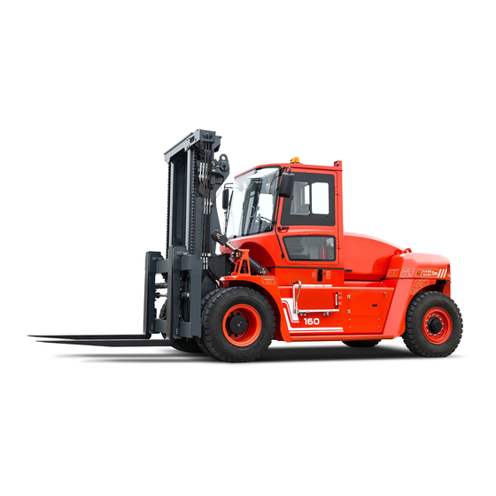
HELI CPCD120-C2Z-09 Operation & Service Manual
Counterbalanced type forklift truck with engine 12-20t
Hide thumbs
1
2
Table Of Contents
3
4
5
6
7
8
9
10
11
12
13
14
15
16
17
18
19
20
21
22
23
24
25
26
27
28
29
30
31
32
33
34
35
36
37
38
39
40
41
42
43
44
45
46
47
48
49
50
51
52
53
54
55
56
57
58
59
60
61
62
63
64
65
66
67
68
69
70
71
72
73
74
75
76
77
78
79
80
81
82
83
84
85
86
87
88
89
90
91
92
93
94
95
96
97
98
99
100
101
102
103
104
105
106
107
108
109
110
111
112
113
114
115
116
117
118
119
120
121
122
123
124
125
126
127
128
129
130
131
132
133
134
135
136
137
138
139
140
141
142
143
144
145
146
147
148
149
150
151
152
153
154
155
156
157
158
page
of
158
Go
/
158
Contents
Table of Contents
Bookmarks
Table of Contents
Table of Contents
I Safe Operation Procedures and Daily Maintenance of Forklift Truck
Main Technical Parameters of Forklift Truck
Introduction to Main Components of Forklift Trucks
Structure, Principle, Adjustment and Maintenance of Forklift Trucks
Power System
Transmission Device
Drive Axle
Steering System
Steering Axle
Brake System
Electrical System
Fuel Gauge
Hydraulic System
Lifting System
Cab Tilting System
Operation Instructions for DPF Regeneration of Heavy-Duty Euro V/China IV Diesel
Engines
Advertisement
Quick Links
1
I Safe Operation Procedures and Daily Maintenance of Forklift Truck
2
Main Technical Parameters of Forklift Truck
3
Power System
4
Electrical System
Download this manual
OPERATION & SERVICE
MANUAL
Counterbalanced Type Forklift Truck with Engine
12-20t
Table of
Contents
Previous
Page
Next
Page
1
2
3
4
5
Advertisement
Table of Contents
Need help?
Do you have a question about the CPCD120-C2Z-09 and is the answer not in the manual?
Ask a question
Questions and answers
Related Manuals for HELI CPCD120-C2Z-09
Forklifts HELI CPCD 20 Manual
(98 pages)
Forklifts HELI CPCD 25 Manual
(98 pages)
Forklifts HELI CPCD 35 Manual
(98 pages)
Forklifts HELI CPCD150 Manual
Forklift truck (61 pages)
Forklifts HELI CPCD180EC Series Manual
(57 pages)
Forklifts HELI CPCD160-C2Z-06 Operation & Service Manual
Counterbalanced type forklift truck with engine 12-20t (158 pages)
Forklifts HELI CPCD50-CU1Y4G3 Operation & Maintenance Manual
Rough terrain forklift with engine 5t (179 pages)
Forklifts HELI G Series Operation And Service Manual
Rough terrain forklift 2.0-3.5 ton (90 pages)
Forklifts HELI CPCD35Y Operation And Service Manual
Rough terrain forklift 2.0-3.5 ton (90 pages)
Forklifts HELI H3 Series Manual
(75 pages)
Forklifts HELI H Series Manual
Internal combustion counterbalanced forklift trucks (77 pages)
Forklifts HELI CPCD50-M2 Manual
Internal combustion counterbalanced forklift trucks (77 pages)
Forklifts HELI G3 Series Operation & Service Manual
Internal combustion counterbalanced forklift truck 2-3.5t (139 pages)
Forklifts HELI G3 Series Operation & Service Manual
Internal combustion counterbalanced forklift truck(standard) 2-3.5t (199 pages)
Forklifts HELI CPCD20 Operation & Service Manual
Internal combustion counterbalanced forklift truck(standard) 2-3.5t (199 pages)
Forklifts HELI CPCD25 Operation & Service Manual
Internal combustion counterbalanced forklift truck(standard) 2-3.5t (199 pages)
This manual is also suitable for:
Cpcd120-czg-09
Cpcd135-c2z-06
Cpcd135-czg-06
Cpcd150-c2z-06
Cpcd150-czg-06
Cpcd160-c2z-06
...
Show all
Cpcd160-czg-06
Cpcd140-c2z-09
Cpcd140-czg-09
Cpcd150-c2z-09
Cpcd150-czg-09
Cpcd160-c2z-09
Cpcd160-czg-09
Cpcd140-c2z-12
Cpcd140-czg-12
Cpcd150-c2z-12
Cpcd150-czg-12
Cpcd160-c2z-12
Cpcd160-czg-12
Cpcd14-c2z-12
Cpcd14-czg-12
Cpcd180-czg-12
Cpcd180-cz1g-12
Cpcd200-czg-12
Cpcd200-cz1g-12
Table of Contents
Print
Rename the bookmark
Delete bookmark?
Delete from my manuals?
Login
Sign In
OR
Sign in with Facebook
Sign in with Google
Upload manual
Upload from disk
Upload from URL


Need help?
Do you have a question about the CPCD120-C2Z-09 and is the answer not in the manual?
Questions and answers