
Subscribe to Our Youtube Channel
Related Manuals for TE Connectivity FDH 3000 864


Summary of Contents for TE Connectivity FDH 3000 864
- Page 1 FDH 3000 864 Termination Cabinet User Manual ADCP-96-088 Issue 2 6/2013 21607-A 300001777717 Rev A...
- Page 2 Contents herein are current as of the date of publication. TE Connectivity reserves the right to change the contents without prior notice. In no event shall TE Connectivity be liable for any damages resulting from loss of data, loss of use, or loss of profits and TE Connectivity further disclaims any and all liability for indirect, incidental, special, consequential or other similar damages.
-
Page 3: Table Of Contents
FDH 3000 864 Termination Cabinet ........ - Page 4 ADCP-96-088 • Issue 2 • 6/2013 • Preface TABLE OF CONTENTS TABLE OF CONTENTS Content Page Sliding Adapter Pack Pass-Through Routing Procedure ........39 MAINTENANCE AND REPAIR PROCEDURES .
-
Page 5: About This Manual
ADCP-96-088 • Issue 2 • 6/2013 • Preface ABOUT THIS MANUAL This publication describes the OmniReach 864 termination FDH 3000 cabinet. Also included are procedures for mounting the cabinet, installing additional splitter modules, installing additional distribution panels, storing the splitter output fibers, connecting the splitter output fibers to the distribution fibers, and replacing damaged components. -
Page 6: Standards Certification
ADCP-96-088 • Issue A • June 2001 • Preface Danger: Do not look into the ends of any optical fiber. Exposure to laser radiation may result. Do not assume the laser power is turned-off or that the fiber is disconnected at the other end. Danger: Use adequate lifting equipment when moving or installing Fiber Distribution Hub cabinets. -
Page 7: Description
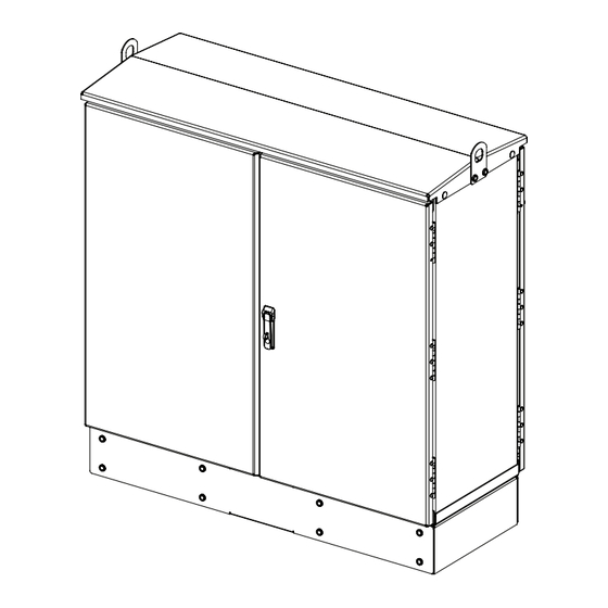
A typical cabinet is shown in Figure The interior of the FDH 3000 864 termination cabinet consists of the following primary components: Distribution Panels: Provide a point for connecting the splitter output fibers with the terminated distribution cable fibers. - Page 8 FRONT OF THE CABINET. THIS PROVIDES ACCESS TO MOST OF THE COMPONENTS MOUNTED WITHIN THE CABINET. SLIDING SLIDING ADAPTER PACK ADAPTER PACK BACK 21625-C Figure 1. FDH 3000 864 Termination Cabinet Page 2 © 2013, Tyco Electronics Corporation. All Rights Reserved.
- Page 9 ADCP-96-088 • Issue 2 • 6/2013 The cabinet may be mounted on a concrete pad or on a polymer concrete mounting sleeve. Mounting kits (accessories) are available for each mounting option. The feeder and distribution cables enter/exit the cabinet from the bottom. Clamps secure the cables to the inside of the cabinet.
- Page 10 ADCP-96-088 • Issue 2 • 6/2013 19.58 IN (49.7 CM) 42.53 IN 48.74 IN (108.0 CM) (123.8 CM) 47.39 IN 16.68 IN 21604-A (120.4 CM) (42.37 CM) Figure 2. 864 Termination FDH 3000 Cabinet Dimensions Page 4 © 2013, Tyco Electronics Corporation. All Rights Reserved.
-
Page 11: Before Starting The Installation
ADCP-96-088 • Issue 2 • 6/2013 2 BEFORE STARTING THE INSTALLATION This section provides general installation considerations, unpacking and inspection procedures, and lists the tools and materials required for cabinet installation. Installation Overview Installation of the 864 termination FDH 3000 cabinet involves the following main tasks: Installing a Support Base (Pedestal-Mount) –... -
Page 12: Cabinet Installation Hardware
ADCP-96-088 • Issue 2 • 6/2013 Cabinet Installation Hardware The cabinet is shipped with various parts (see Table 2) that are used for securing the cabinet to the FMS or PMF. Verify that the parts specified are received. Table 2. Cabinet Installation Hardware ITEM QUANTITY 3/8 x 1-inch hex head capscrews... -
Page 13: Cabinet Mounting
ADCP-96-088 • Issue 2 • 6/2013 Mounting Sleeve Installation • Mounting Sleeve kit (FMS-FD3J-KIT-A) • Stone aggregate • Tamping equipment • Hole saw and drill (use to cut holes for cable conduit if pre-drilled holes are not usable) Concrete Pad Installation •... -
Page 14: Mounting The Cabinet On A Mounting Sleeve
ADCP-96-088 • Issue 2 • 6/2013 3 MOUNTING THE CABINET ON A MOUNTING SLEEVE The FMS, shown in Figure 3, is a polymer concrete sleeve that may be used to support the cabinet at ground level. The FMS may also be used as a splicing vault. Four vertical racks are molded into the sides of the FMS to accommodate removable rungs (not provided). -
Page 15: Placement Of The Fms
ADCP-96-088 • Issue 2 • 6/2013 VERTICAL RACKS CONDUIT TOPSOIL OR FOR MANHOLE ENTRANCE DECORATIVE ROCK CABLE SUPPORT BARS HOLES GRADE SIDE VIEW 49.25 IN (125 CM) STONE AGGREGATE FILL COMPACTED SOIL 12 IN (30.5 CM) 90 IN. (229 CM) CONDUIT ENTRANCE HOLES... -
Page 16: Cable Conduit Installation
ADCP-96-088 • Issue 2 • 6/2013 3. Use a carpenter’s level to verify that the FMS is level. If it is necessary to add or remove fill for leveling, tamp any added fill to maintain the base stability. Cable Conduit Installation Select the conduit entrance holes (see Figure 4) for the OSP feeder and distribution cables. - Page 17 ADCP-96-088 • Issue 2 • 6/2013 864 TERMINATION FDH 3000CABINET (REAR) CAPSCREWS (8), LOCK WASHERS (8), FLAT WASHERS (8) GROUND SPACER (ACCESSORY) CAPSCREWS (8), FMS SLEEVE LOCK WASHERS (8), COVER FLAT WASHERS (8) ISOLATION GASKET GROUNDING WIRE FMS ADAPTER COVER FEEDER AND DISTRIBUTION CABLES...
- Page 18 ADCP-96-088 • Issue 2 • 6/2013 Use the following procedure to mount the cabinet on the FMS: 1. Use a 3/16-inch hex-key to remove the screws that secure the access covers to the front and back sides of the cabinet ground spacer/riser as shown in Figure 21608-A Figure 6.
-
Page 19: Grounding Wire Connection To Cabinet
ADCP-96-088 • Issue 2 • 6/2013 10. Feed the stubbed feeder and distribution cables into the appropriate conduit sections and route to the splice enclosure (not provided). Some excess cable slack may be stored in the bottom of the FMS. Note: A separate splice enclosure (not provided) is required for splicing the cabinet OSP cables to the network OSP cables. - Page 20 ADCP-96-088 • Issue 2 • 6/2013 CABINET GROUNDING LUG (#6 - #14 AWG WIRE) 21639-D GROUNDING WIRE ENTRY POINT GROUNDING WIRE ROUTED TO GROUNDING BUS BAR Figure 7. Grounding Wire Connection To Grounding Bus Bar Page 14 © 2013, Tyco Electronics Corporation. All Rights Reserved.
-
Page 21: Mounting The Cabinet On A Concrete Pad
ADCP-96-088 • Issue 2 • 6/2013 4 MOUNTING THE CABINET ON A CONCRETE PAD The Pad Mount Frame (PMF), shown in Figure 8, is a stainless steel frame that provides a mounting base for the cabinet when embedded in a concrete foundation. Caution: Mounting the cabinet directly on a concrete pad may cause chemical corrosive action to the cabinet. - Page 22 ADCP-96-088 • Issue 2 • 6/2013 64 IN (162.6 CM) 26.9 IN 4 INCH DUCTS FOR RIGHT SIDE (68.4 CM) FEEDER/DISTRIBUTION CABLES (USE DUCT B FOR RIGHT SIDE 21.9 IN CUSTOMER-INSTALLED FEEDER) (55.7 CM) 7.6 IN (19.1 CM) 23 IN 4 IN DUCTS FOR LEFT SIDE (58.4 CM) FEEDER/DISTRIBUTION CABLES...
-
Page 23: Concrete Pad Construction
ADCP-96-088 • Issue 2 • 6/2013 LOCATION OF 4-INCH DUCTS FOR LOCATION OF 4-INCH DUCTS FOR LEFT SIDE FEEDER AND DIST CABLES RIGHT SIDE FEEDER AND DIST CABLES (USE DUCT A FOR LEFT SIDE FEEDER) (USE DUCT B FOR RIGHT SIDE FEEDER) PLACE CARDBOARD FRONT OF ALIGN HOLES IN... -
Page 24: Grounding System Installation
ADCP-96-088 • Issue 2 • 6/2013 DIMENSIONS SHOW FINISHED 64 IN. SIZE OF CONCRETE PAD 162.6 CM) 64 IN. (162.6 CM) F R O 21714-C 2 x 6 FRAMING FOR FORM PAD MOUNT FRAME (PMF) LEVELING STAKES TEMPORARY (4 PLACES) SUPPORT WIRES (4 PLACES) Figure 11. - Page 25 ADCP-96-088 • Issue 2 • 6/2013 864 TERMINATION FDH 3000 CABINET (FRONT) MOUNTING BOLTS (EIGHT PLACES) MOUNTING BOLTS GROUND SPACER (EIGHT PLACES) (OPTIONAL ACCESSORY) ISOLATION PLACE NOTCH ON GASKET REAR SIDE OF CABINET REAR GROUND CABLE CONDUIT 21715-A PAD MOUNTING FRAME (PMF) CONCRETE FRONT...
- Page 26 ADCP-96-088 • Issue 2 • 6/2013 21608-A Figure 13. Removing Access Covers From Ground Spacer/Riser 3. Place the isolation gasket (provided with cabinet) on the PMF and align the holes in the gasket with the holes in the PMF. Make sure the side of the gasket with the cut-out section is on the side of the PMF that corresponds to the rear side of the cabinet.
-
Page 27: Grounding Wire Connection To Cabinet
ADCP-96-088 • Issue 2 • 6/2013 Grounding Wire Connection To Cabinet Prior to mounting the cabinet, a grounding system and grounding wire should have been installed (see Section 4.4) in the space below the cabinet. Use the following procedure to connect the grounding wire to the cabinet: 1. -
Page 28: Feeder And Distribution Cable Configuration Information
ADCP-96-088 • Issue 2 • 6/2013 5 FEEDER AND DISTRIBUTION CABLE CONFIGURATION INFORMATION The 864 termination FDH 3000 cabinet is equipped with pre-installed OSP feeder and distribution cables. The cable stub ends must be spliced to the network feeder and distribution cables at a separate splice enclosure (not provided). -
Page 29: Osp Distribution Cable Configuration
ADCP-96-088 • Issue 2 • 6/2013 OSP Distribution Cable Configuration Each distribution cable has a fiber count that is a multiple of 72. From 1 to 12 distribution cables may be present depending on the number of distribution panels ordered and the cable fiber count. -
Page 30: Plug And Play Splitter Module Installation
ADCP-96-088 • Issue 2 • 6/2013 6 PLUG AND PLAY SPLITTER MODULE INSTALLATION The 864 termination FDH 3000 cabinet can accommodate up to forty-eight splitter modules. Depending on the splitter type, plug and play splitter modules are equipped with either one or two input connectors. - Page 31 ADCP-96-088 • Issue 2 • 6/2013 LEFT SWING FRAME SPLITTER COMPARTMENTS SLOT NUMBERS SHOWN SLOT NUMBERS SHOWN FOR REFERENCE ONLY FOR REFERENCE ONLY SPLITTER INSTALLED RIGHT SWING FRAME SPLITTER COMPARTMENTS IN SLOT 1 SLOT NUMBERS SHOWN SLOT NUMBERS SHOWN FOR REFERENCE ONLY FOR REFERENCE ONLY PLUG AND PLAY DUST CAP ASSEMBLY...
- Page 32 ADCP-96-088 • Issue 2 • 6/2013 CONNECTOR KEYWAY REAR VIEW OF 21358-D SPLITTER COMPARTMENT Figure 19. Feeder Cable Connector 5. Clean the feeder cable connector(s) as specified in the Optical Fiber Systems Cleaning and Mating Instructions (ADCP-90-159). 6. Reinstall the feeder cable connector(s) at the rear of the splitter compartment. 7.
-
Page 33: Distribution Panel Installation
ADCP-96-088 • Issue 2 • 6/2013 7 DISTRIBUTION PANEL INSTALLATION The 864 termination FDH 3000 cabinet may be ordered with up to twelve 72-position distribution panels pre-installed in the cabinet. If the cabinet is equipped with less than twelve panels, additional panels may be installed as needed. When ordered separately, distribution panels are pre-cabled for quick installation in unused mounting slots. - Page 34 ADCP-96-088 • Issue 2 • 6/2013 Note: Figure 21 shows how to remove the entry/exit hole cover for distribution cables 1–6. The entry/exit hole cover for distribution cables 7–12 is mounted on the opposite side of the cabinet center partition and may be removed using the same basic procedure. 4.
- Page 35 ADCP-96-088 • Issue 2 • 6/2013 8. Using the two screws provided, secure the cable clamp plate (attached to cable) to the cabinet center partition. 9. Assemble the two cable clamps (and grommets if required) on the cable as shown in Figure CABLE USE GROMMET...
- Page 36 ADCP-96-088 • Issue 2 • 6/2013 NOTE: THIS DRAWING SHOWS THE SWING FRAME FOR PANELS 7 - 12. THE SAME BASIC INSTALLATION PROCEDURE APPLIES TO THE SWING FRAME FOR PANELS 1 - 6. OPEN SWING FRAME AND INSERT PANEL INTO MOUNTING SLOT FROM THIS SIDE PUSH-PIN FASTENERS FOR PANEL 12 (3 PLACES)
- Page 37 ADCP-96-088 • Issue 2 • 6/2013 15. Route and secure the distribution cable subunit fibers within the cabinet as shown in Figure 26 Figure FEEDER 1 PANEL 6 PANEL 5 PANEL 4 PANEL 3 PANEL 2 PANEL 1 LEFT SWINGFRAME PANELS 1 - 6 NOTE: SHOWN WITH CABINET ENCLOSURE...
- Page 38 ADCP-96-088 • Issue 2 • 6/2013 PANEL 12 PANEL 11 PANEL 10 PANEL 9 PANEL 8 PANEL 7 RIGHT SWINGFRAME PANELS 7 - 12 NOTE: SHOWN WITH 21822-A CABINET ENCLOSURE REMOVED. Figure 27. Route and Secure Distribution Cable Subunits - (Panels 7 – 12) 19.
- Page 39 ADCP-96-088 • Issue 2 • 6/2013 WEATHER-SEAL STRIP GROUNDING SYSTEM JUMPER CABLE ROUTING FOR OPTICAL CABLE #8 21820-A Figure 28. Cable Grounding System - Interior View 21. Open the grounding system access cover located on the rear side of the cabinet as shown in Figure 22.
- Page 40 ADCP-96-088 • Issue 2 • 6/2013 CABLE 2 CABLE 1 CABLE 16 CABLE 15 TIGHTEN TO 30 TO 35 21823-A LBS FORCE - INCHES (3.4 TO 4.0 Nm) OF TORQUE LEFT BUS BAR RIGHT BUS BAR CABLE ASSEMBLY CABLE ASSEMBLY Figure 29.
-
Page 41: Routing And Connecting The Splitter Output Fibers
ADCP-96-088 • Issue 2 • 6/2013 8 ROUTING AND CONNECTING THE SPLITTER OUTPUT FIBERS The splitter modules are mounted at the top of the 864 termination FDH 3000 cabinet. When a splitter module is initially installed, the output fibers are routed to the storage panel located at the bottom of the cabinet. -
Page 42: Enabling Service To A Subscriber
ADCP-96-088 • Issue 2 • 6/2013 Enabling Service To a Subscriber Use the following procedure to enable service to a subscriber: 1. Check the designation labels on the cabinet front doors to determine the distribution panel and port number that corresponds to the address of the subscriber. 2. - Page 43 ADCP-96-088 • Issue 2 • 6/2013 21629-C Figure 32. Routing Splitter Output Fibers - Splitter and Distribution Port on Opposite Sides of Cabinet Page 37 © 2013, Tyco Electronics Corporation. All Rights Reserved.
-
Page 44: Pass-Through Routing Procedure
ADCP-96-088 • Issue 2 • 6/2013 9 PASS-THROUGH ROUTING PROCEDURE Pass-through routing is used when it is necessary for a feeder cable optical signal to be routed directly to a distribution port. This involves connecting a patch cord between the terminated feeder cable connector and the appropriate distribution port. -
Page 45: Sliding Adapter Pack Pass-Through Routing Procedure
ADCP-96-088 • Issue 2 • 6/2013 ORIENT CONNECTOR SO KEY IS ON TOP 21365-B Figure 33. Installing Patch Cord Connector in Dust Cap Assembly DUST CAP AND CONNECTOR ASSEMBLY 21826-A Figure 34. Inserting Dust Cap Assembly into Splitter Compartment Sliding Adapter Pack Pass-Through Routing Procedure Use the following procedure to route a jumper patch cord between the feeder cable sliding adapter pack and one of the distribution panels. - Page 46 ADCP-96-088 • Issue 2 • 6/2013 REMOVE DUST CAP PULL UPWARD ON TAB INSERT CONNECTOR 21827-A Figure 35. Adapter Pack Raised to Access Position Warning: Infrared radiation is invisible and can seriously damage the retina of the eye. Do not look into the ends of any optical fiber.
- Page 47 ADCP-96-088 • Issue 2 • 6/2013 11. Refer to the procedures in Section 8.2 to route the pass-through patch cord to the distribution panel and to connect the patch cord connector to the appropriate optical port. PASS-THROUGH ROUTING FOR PATCH CORDS SLIDING ADAPTER PACK...
- Page 48 ADCP-96-088 • Issue 2 • 6/2013 PASS-THROUGH ROUTING FOR PATCH CORDS SLIDING ADAPTER PACK 21824-A Figure 37. Routing Patch Cord Through Left Swing Frame Page 42 © 2013, Tyco Electronics Corporation. All Rights Reserved.
-
Page 49: Maintenance And Repair Procedures
ADCP-96-088 • Issue 2 • 6/2013 10 MAINTENANCE AND REPAIR PROCEDURES The 864 termination FDH 3000 cabinet requires no regular maintenance to insure continuous and satisfactory operation. Maintenance is limited to repairing or replacing any cabinet components that may be damaged or broken in the course of normal operation. The following sections provide procedures for repairing or replacing common cabinet components. -
Page 50: Splitter Compartment Adapter Replacement
ADCP-96-088 • Issue 2 • 6/2013 2. Unlatch and fully open the cabinet swing frame to provide access to the rear side of the distribution panel. 3. Disconnect the distribution connector from the rear side of the broken adapter and install a dust cap on the connector. -
Page 51: Replacing A Damaged Fiber Or Connector
ADCP-96-088 • Issue 2 • 6/2013 DUST CAP OR SPLITTER THUMB SCREW FEEDER CABLE CONNECTOR ADAPTER ASSEMBLY REAR VIEW OF 21407-A SPLITTER COMPARTMENT Figure 39. Splitter Compartment Adapter Replacement 6. Install the replacement adapter assembly in the splitter compartment and secure it by turning the thumbscrew counter-clockwise until tight. -
Page 52: Splitter Output Fiber Connector Replacement
ADCP-96-088 • Issue 2 • 6/2013 10.4.1 Splitter Output Fiber Connector Replacement Use the following procedure to replace the connector: 1. Disconnect the damaged connector and the good connector from the adapter and install a dust cap on the good connector. Warning: Infrared radiation is invisible and can seriously damage the retina of the eye. - Page 53 ADCP-96-088 • Issue 2 • 6/2013 GROUNDING GROUNDING STRAP LUG STRAP LUG DOOR DOOR HINGES HINGES 21628-B DOOR DOOR LINKAGE LINKAGE Figure 40. Door Replacement DOOR LINKAGE BUSHING FLAT WASHER LOCK NUT 21683-A Figure 41. Door LInkage Hardware Page 47 ©...
-
Page 54: Grounding System Terminal Access Procedure
ADCP-96-088 • Issue 2 • 6/2013 5. Carefully lift the door away from the cabinet. 6. Transfer all designation information that may be recorded on the damaged door to the labels on the replacement door. 7. Place the replacement door in position for installation on the hinges. 8. - Page 55 ADCP-96-088 • Issue 2 • 6/2013 CABLE 2 CABLE 1 CABLE 16 CABLE 15 TIGHTEN TO 30 TO 35 21823-A LBS FORCE - INCHES (3.4 TO 4.0 Nm) OF TORQUE LEFT BUS BAR RIGHT BUS BAR CABLE ASSEMBLY CABLE ASSEMBLY Figure 42.
-
Page 56: Customer Information And Assistance
ADCP-96-088 • Issue 2 • 6/2013 11 CUSTOMER INFORMATION AND ASSISTANCE PHONE: U.S.A. or CANADA Sales: 1-800-366-3891 Extension 73000 (Direct 1-952-917-3000) Technical Assistance: 1-800-366-3891 Extension 73475 (Direct 1-952-917-3475) WRITE: Tyco Electronics Corporation PO Box 1101, Minneapolis, MN 55440-1101, USA PRODUCT INFORMATION AND TECHNICAL ASSISTANCE: telnet.tac@te.com REPRINTS: PDF copies of manuals are available...
Need help?
Do you have a question about the FDH 3000 864 and is the answer not in the manual?
Questions and answers