Advertisement
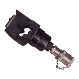
Nest Wheel
Lock
Collar
Hose Assembly
or Handle Control
Figure 1
1. INTRODUCTION
This instruction sheet provides application,
maintenance, and inspection procedures for DYNA-
CRIMP* Crimping Head 69069 (see Figure 1). The
tool is used to crimp SOLISTRAND* Terminals and
splices onto solid or stranded copper wire sizes 8
AWG through 4/0 AWG. See Instruction Sheet
408-9786.
The crimping head is designed for use with Hydraulic
Power Unit 69120-[ ] described in Customer Manual
409-1950. Read these instructions, and all applicable
references, before inserting the nest or indenter and
crimping any terminals or splices.
NOTE
i
NOTE
Dimensions on this sheet are in millimeters [with inches
in brackets]. Figures and illustrations are for reference
only and are not drawn to scale.
Reasons for reissue are provided in Section 9,
REVISION SUMMARY.
© 2012 Tyco Electronics Corporation, a TE Connectivity Ltd. company
All Rights Reserved
*Trademark
TE Connectivity, TE connectivity (logo), and TE (logo) are trademarks. Other logos, product and/or company names may be trademarks of their respective owners.
Hydraulic Crimping Head 69069
2. DESCRIPTION
Latch
Main components of the crimping head are: a yoke
which houses the indenter and retains the terminal
assembly for crimping, a latch which allows pivoting of
the yoke on the pivot pin (typically required for splice
Thumb Knob
terminations), a cylinder which contains the head's
hydraulic chamber, a piston (ram) which holds and
controls the indenter, and a quick connect/disconnect
coupler (cylinder half) which mates with the coupler on
hose or handle control to release or supply pressure.
3. CRIMPING HEAD INSTALLATION
Each crimping head is shipped with a coating of
Dust Cap
lubricating oil to prevent rust and corrosion. Wipe the
oil off before installing the crimping head on the power
unit. Note that the crimping head is shipped without oil
inside the cylinder. To install crimping head, proceed
as follows.
TOOLING ASSISTANCE CENTER 1-800-722-1111
PRODUCT INFORMATION 1-800-522-6752
DANGER
To avoid personal injury when using DYNA-CRIMP
equipment:
- Do NOT modify the crimping equipment in any
way.
- Use only the nest and indenter, terminals, and
wire specified for the head.
- Do NOT perform repairs other than those
specified in the instructional material supplied with
the equipment.
DANGER
Make sure that hydraulic pressure to hose or handle
control is released and that power supply is
disconnected to electric power unit, if applicable.
1. Thoroughly clean the coupling area of the handle
control or hose assembly and crimping head.
2. Remove protective dust caps from both quick
connect/disconnect couplers.
3. Hold hose or handle control vertically to prevent
oil spillage. Attach hose or handle control to
coupling section on head. Thread properly and
tighten the collar.
CAUTION
Oil flow must be unobstructed between power unit and
crimping head. Make sure that all couplers are fully
mated and tightened.
This controlled document is subject to change.
For latest revision and Regional Customer Service,
visit our website at www.te.com
Instruction Sheet
408-1745
19 DEC 12 Rev D
1 of 7
Advertisement
Table of Contents

Related Manuals for TE Connectivity 69069


Summary of Contents for TE Connectivity 69069
- Page 1 All Rights Reserved PRODUCT INFORMATION 1-800-522-6752 For latest revision and Regional Customer Service, *Trademark visit our website at www.te.com TE Connectivity, TE connectivity (logo), and TE (logo) are trademarks. Other logos, product and/or company names may be trademarks of their respective owners.
-
Page 2: Crimping Procedure
408-1745 DANGER WIRE STRIP LENGTH If crimping head must be removed after being in WIRE production, pressure must be released in the hydraulic Terminals Butt and Parallel Splices SIZE system before head is removed. Min. Max. Min. Max. - If using Hydraulic Power Unit 69120-[ ], DISCONNECT POWER UNIT FROM POWER 8.38 9.14... - Page 3 408-1745 3. Insert the stripped wire into the wire barrel of barrel. When crimping butt splices, wire must be terminal or splice. When crimping terminals and visible through the inspection hole.Activate the parallel splices, the end of the wire must be flush power unit to complete the crimp.
-
Page 4: Inspection & Maintenance
408-1745 4. Activate the power unit to complete the crimp. Chipped Flattened Area Area 5. To complete the other half of the butt splice, remove and reposition the uncrimped half of the splice in the nest. Insert the wire and then activate the power unit to crimp the splice. - Page 5 408-1745 Suggested Plug Gage Design NO-GO Dimension GO Dimension Die Closure Configuration BARREL CRIMP GAGE MEMBER DIMENSIONS “B” DIMINSIONS “A” RADIUS “R” SIZE NO-GO NO-GO 2.11[.083] 2.54 [.100] 2.184 - 2.192 [.0860 - .0863] 2.537 - 2.540 [.0999 - .1000] 3.58 [.141] 3.12 [.123] 3.48 [.137]...
-
Page 6: Section 8, Replacement And Repair
408-1745 7.4. Crimping Head Check-Out Procedure CUSTOMER SERVICE (038-035) TYCO ELECTRONICS CORPORATION If the ram fails to return to the DOWN position after PO BOX 3608 completion of a crimping cycle, the cause may be in HARRISBURG PA 17105-3608 the crimping head. To determine whether or not the trouble is in the crimping head, release pressure in the Tools may also be returned for evaluation and repair. - Page 7 408-1745 QTY PER ITEM PART NUMBER DESCRIPTION CRIMPING NUMBER HEAD 311471-1 QUICK-COUPLER, Cylinder Half 47322 INDENTER 301707 PIN, Retaining 301712 SPRING 304028 STOP, Spring 2-305927-5 SCREW, Button Head, 10-32 UNF X .31 Inches Long 304029 SPRING 3-21028-5 PIN, Roll, .094 Inches, Dia X .438 Inches Long 1-21045-3 RING, Retaining 2-21028-4...
Need help?
Do you have a question about the 69069 and is the answer not in the manual?
Questions and answers