
Related Manuals for ITRON 100G Series


Summary of Contents for ITRON 100G Series
- Page 1 Natural Gas Solutions 100G Series Gas ERT Module Installation Guide, Remote Mount TDC-0824-014...
- Page 2 All product returns must be shipped by ground transportation. Modifications and Repairs To ensure system performance, this device and antenna shall not be changed or modified without the expressed approval of Itron. Any unauthorized modification will void the user's authority to operate the equipment.
- Page 3 36 inches. Product warranty coverage is contingent on not exceeding this drop height limitation. Suggestions If you have comments or suggestions on how we may improve this documentation, send them to TechnicalCommunicationsManager@itron.com. If you have questions or comments about the software or hardware product, contact Itron Technical Support: Contact Internet: www.itron.com...
- Page 4 TDC-0824-014 100G Series Gas ERT Module Installation Guide, Remote Mount Proprietary and Confidential...
-
Page 5: Table Of Contents
Rotary Meter Installation ..................... 18 Required Installation Materials Available from Itron ................19 Connecting the 100G Series Gas ERT Module to the GE Dresser Rotary Meter Cable ....19 Connecting and Installing the GE Dresser D800/D1000 Meter ............21 Connecting and Installing the 100G Series Module to the GE Dresser ES3 or ETC......26 Configuring Index Settings Using the GE Dresser MeterWare Software .......... - Page 6 Eagle Research Meter Installation ..................58 Required Materials ......................58 100G Series Communications with the Eagle Research Corrector ......63 100G Series Remote Module Installation to the Romet AdEM Using a Cannon or PG9 Factory-Installed Pigtail Cable ....................69 Required Materials ......................70 Meter Preparation ......................
-
Page 7: Before You Begin
This installation guide refers to all models of the 100G remote ERT module as the 100G series remote gas module. Mechanical and electrical installation procedures are identical. For more information about ERT to meter compatibility, see the... - Page 8 Before You Begin TDC-0824-014 100G Series Gas ERT Module Installation Guide, Remote Mount viii Proprietary and Confidential...
-
Page 9: About The 100G Series Gas Ert Module
ERT module. 100G ERT module circuitry senses an electrical current break to report a cut cable tamper event. Transmission Modes The 100G series remote gas module can be set to transmit in fixed network, mobile and handheld, hard to read mobile and handheld, or cellular solutions mode (fixed network applications only). •... -
Page 10: 100G Dls Ert Module And Itron Security Manager
100G DLS security at the time the ERT module is deployed or at a later time using an Itron programming device, Field Deployment Manager Endpoint Tools Enhanced, and programming commands. Initial key exchange commands are secured using the utility factory keys. -
Page 11: 100G Series Gas Ert Module Specifications
Field Deployment Manager Field Representative's Guide TDC-0936-XXX Note The last three digits of the user and installation guides represent the document's revision level. The revision level is subject to change without notice. TDC-0824-014 100G Series Gas ERT Module Installation Guide, Remote Mount Proprietary and Confidential... -
Page 12: 100G Series Remote Ert Module Meter Compatibility List
About the 100G Series Gas ERT Module 100G Series Remote ERT Module Meter Compatibility List The following table lists meter types compatible with the 100G series remote gas module. Due to continuous research, product improvements and enhancements, Itron reserves the right to change product or system specifications without notice. - Page 13 Mini-Max only, Item #115 must be set at 1 or 2. Item 124 wake up setting on Honeywell corrector must be set to 1. Compatible corrector firmware versions are 2.5020 and 2.73. TDC-0824-014 100G Series Gas ERT Module Installation Guide, Remote Mount Proprietary and Confidential...
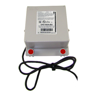
- Page 14 Where direct mount solution is not 100G Remote ERG-5000-501 compatible. 100G Datalogging Remote ERG-5002-501 100G Datalogging FN Remote ERG-5003-501 100G DLS Datalogging Remote ERG-5006-501 100G DLT Datalogging Remote ERG-5007-501 TDC-0824-014 100G Series Gas ERT Module Installation Guide, Remote Mount Proprietary and Confidential...
-
Page 15: Installation Prerequisites
100G DLT Datalogging Remote ERG-5007-503 (Cubic foot) Installation Prerequisites The following tools are required to install, program, and check the remote 100G series remote gas module. Some specific tools may be required dependent on meter or instrument type. • Medium flat-blade screwdriver •... - Page 16 Warning ERT modules contain sensitive electronic components which can be damaged if the module is dropped from heights greater than 36 inches. Product warranty coverage is contingent on not exceeding this drop height limitation. TDC-0824-014 100G Series Gas ERT Module Installation Guide, Remote Mount Proprietary and Confidential...
-
Page 17: Mounting The 100G Series Gas Ert Module
H A P T E R Mounting the 100G Series Gas ERT Module This chapter provides the instructions to mount the 100G series remote gas module on a pipe or other flat vertical surface (wall). Installation Options Mount the remote ERT module using the pipe mount or wall mount (flat vertical surface) procedure. -
Page 18: Mounting Installation Considerations
Violating the mounting orientation requirements may void the product warranty Mounting the Remote ERT Module on a Pipe The following items are required to mount the 100G series remote gas module on a pipe or vertical flat surface (wall): Itron Part... -
Page 19: Adapter Plate Mounting Positions
The module's arrow must never point to either side or upside down. The module's tilt tamper functionality is designed to operate with the module installed vertically. 1. Remove the pipe bracket and band clamp from the Pipe Mount Installation Kit (Itron part number CFG- 0005-003). - Page 20 To mount the adapter plate on the pipe bracket Caution Vertical mounting position is important to maximize RF performance. Mount the 100G series remote gas module with the module label arrow pointing up. The module's arrow must never point to either side or upside down.
- Page 21 3. Tighten both screws securely in an alternating pattern. Tighten to 9 - 12 inch-pounds torque. To mount the 100G series remote gas module on the adapter plate 1. Using the ERT module and the two one-inch mounting screws from the Pipe Installation kit, place the back of the remote ERT module against the face of the adapter plate.
- Page 22 To install tamper seals and cable ties 1. Place the new tamper seals from the Pipe Installation Kit over the 100G series remote gas module mounting screws. 2. Firmly push both tamper seals all the way into place with a 1/4-inch nut driver or similar blunt tool.
- Page 23 4. Insert the chiseled end of the cable tie into the locking end and pull the cable tie tight. Cut off and properly dispose the excess cable tie. 100G series remote gas module pipe mount installation is complete. TDC-0824-014 100G Series Gas ERT Module Installation Guide, Remote Mount...
-
Page 24: Mounting The Remote Gas Module On A Wall Or Other Flat Vertical Surface
1. Using one of the three 1-1/2-inch mounting screws from the Pipe Mount Kit, turn the mounting screw for the mounting lug (top of module) part way into the mounting surface. 2. Place the 100G series remote gas module mounting lug recess (on the top of the module backplate) just under the screw head. - Page 25 Mount Installation Kit. Pull the cable tight. Remove and properly dispose the excess cable tie. 100G series remote gas module installation on a vertical flat surface or wall is complete. TDC-0824-014 100G Series Gas ERT Module Installation Guide, Remote Mount...
-
Page 26: Rotary Meter Installation
H A P T E R Rotary Meter Installation This chapter provides the instructions to install the 100G series remote gas module on rotary gas meters. Reference the 100G Series Remote ERT Module Meter Compatibility List on page 4 for rotary meters compatible with the 100G series remote gas module. -
Page 27: Required Installation Materials Available From Itron
Connecting the 100G Series Gas ERT Module to the GE Dresser Rotary Meter Cable You may ship the Itron 100G series remote gas module directly to GE Dresser for a factory-installed cable. If you connect the module to the meter using an existing cable purchased from GE Dresser, complete the following cable installation procedure. - Page 28 Rotary Meter Installation 2. Insert the lead wires from the module into new 3M gel connectors (Itron part number CON-0023-001) together with the same colored lead wire from the meter cable (see the wiring table below) and crimp using a 3M hand-held crimping tool.
-
Page 29: Connecting And Installing The Ge Dresser D800/D1000 Meter
Torque the backplate mounting screws to 9 to 12 inch-pounds. 6. Install the module on the wall or a pipe using the Pipe Installation Kit (Itron part number CFG-0005-003). For mounting instructions, see Mounting the 100G Series Gas ERT Module. - Page 30 2. Loosen the cable gland and pull the cable out until it extends 7.5 to 8" out of the cable gland. 3. Tighten the cable gland. Do not use a plier or wrench to tighten the cable gland. TDC-0824-014 100G Series Gas ERT Module Installation Guide, Remote Mount Proprietary and Confidential...
- Page 31 Gel flowing from the connector provides environmental protection for the connection. Note Connecting the D800 or D1000 to the 100G remote module requires 3M gel cap connectors. Itron supplies the two-wire gel cap connectors. Users who want to complete three-wire connections must supply the 3M UR2 connectors.
- Page 32 4. Carefully fold the ERT module wires into the ERT module housing. Be careful not to pinch the wires or gel connections between the housing and the back plate. TDC-0824-014 100G Series Gas ERT Module Installation Guide, Remote Mount Proprietary and Confidential...
- Page 33 3. Tilt the bottom of the ERT module away from the mounting bracket and slide the notched mounting hub onto the screw and Kep nut. Do not tighten the screw. TDC-0824-014 100G Series Gas ERT Module Installation Guide, Remote Mount Proprietary and Confidential...
-
Page 34: Connecting And Installing The 100G Series Module To The Ge Dresser Es3 Or Etc
Connecting and Installing the 100G Series Module to the GE Dresser ES3 or ETC Meter manufacturers may provide ERT mounting kits and installation procedures. If GE Dresser's 100G series to GE Dresser ES3 or ETC device installation procedure is not available, follow this procedure. - Page 35 Gel flowing from the connector provides environmental protection for the connection. Note Connecting the ES3 or ETC to the 100G remote module requires 3M gel cap connectors. Itron supplies the two-wire gel cap connectors. Users who want to complete three-wire connections must supply the 3M UR2 connectors.
-
Page 36: Configuring Index Settings Using The Ge Dresser Meterware Software
Important This information is subject to change without notice. Refer to the GE Dresser MeterWare product documentation to verify the most current information about programming and configuring the corrector for use with the 100G series remote ERT module. TDC-0824-014 100G Series Gas ERT Module Installation Guide, Remote Mount... - Page 37 1. Select the Configuration tab. 2. Confirm the volume configuration and pulse width settings. 3. Use the drop down lists to change a variable. 4. Click OK to complete the change. TDC-0824-014 100G Series Gas ERT Module Installation Guide, Remote Mount Proprietary and Confidential...
-
Page 38: Programming The Remote Ert Module For Ge Dresser Rotary Meters
Programming the Remote ERT Module for GE Dresser Rotary Meters To program 100G series remote gas modules for use with GE Dresser rotary meters, use the meter drive rates from the drive rate table in this section. B3, LMMA & S3A CTR/TC Meter Drive Rates for Remote ERT Module... -
Page 39: Connecting The Remote Ert Module To The Romet Electronically Compensated Meter (Ecm2®)
Menu items > SET COR OUT. Since Setup Mode is fully configurable, the ECM2 module is ® universally adaptable to all Romet TC meter bodies. Reference the Romet technical manual for specific details on the ECM2 ® TDC-0824-014 100G Series Gas ERT Module Installation Guide, Remote Mount Proprietary and Confidential... -
Page 40: Wiring The 100G Series Gas Ert Module To The Romet Ecm2® Meter
Pipe Installation Kit (Itron part number CFG-0005-003), secure the 100G series remote gas module. Use the cable ties from the kit to secure any excess wire to the piping (see Mounting the Remote ERT Module a Pipe on page 10). -
Page 41: Romet Ecm2/100G Series Gas Ert Module Mounting Option
This mounting procedure requires the Romet ECM2/ERT Mounting Kit (Romet part number 34-444-1-KIT). To mount the 100G series remote gas module on the Romet ECM2 meter 1. Remove the module screw from the back of the ECM2 meter and discard. -
Page 42: Installing The Remote Ert Module To The Elster American Meter Rpm Series Rotary Meter
3. Attach the mounting plate to the meter. Insert the mounting screw where the module screw was removed. Torque the mounting screw to 5-7 ft.lbs. to secure the plate to the Romet meter. 4. Mount the 100G series remote gas module using the pre-drilled holes on the mounting plate and the module mounting screws. - Page 43 Rotary Meter Installation To install the 100G series remote gas module on an Elster American RPM series meter 1. Remove the meter's top plate by removing the two 5mm screws and carefully prying up on the plate. The plate is secured with an o-ring seal. Remove the O-ring from the plate.
- Page 44 1-1/2-inches from the end. Caution Do not cut through the individual wire insulation. 3. Separate the meter cable's black, white, and red wires for connection to the 100G series remote gas module. Cut off the unused wires even with the outer covering (insulation).
- Page 45 Rotary Meter Installation 4. Connect the meter cable to the 100G series remote gas module using 3M gel-cap connectors. Follow the wire connection table and wiring diagrams below. See Installation Prerequisites on page 7 for appropriate 3M crimping tools. Important Use a crimping tool compatible with gel-connectors. Do not use a standard pliers for crimping gel-connects.
-
Page 46: Programming The Remote Ert Module
The Belt Clip Radio connects to the user-supplied laptop using a USB cable or Bluetooth. The 100G DLS ERT modules support enhanced security with the Itron Security Manager. Enabling command or enhanced security requires additional programming. Program the 100G DLS ERT modules using: •... - Page 47 Programming parameters are based on the configuration file loaded into the programming device. During programming, the 100G series remote gas module is set to the nearest 100 cubic feet; the last two digits (tens and units) are programmed as zeros (0). After programming is complete, the ERT module assembly will read to the nearest cubic foot.
- Page 48 Rotary Meter Installation TDC-0824-014 100G Series Gas ERT Module Installation Guide, Remote Mount Proprietary and Confidential...
-
Page 49: Electronic Instrument Installation
H A P T E R Electronic Instrument Installation This section provides the instructions to install the 100G series remote gas module on: • Honeywell Instruments Mini-P, Mini-AT, Mini-Max, and EC-AT volume correctors • Honeywell Instruments Temperature Compensated Indexes (TCI) •... -
Page 50: Installation Prerequisites
100G series remote gas module installation to a volume corrector or instrument requires: • 100G series remote gas module ERT module compatible to a volume corrector or instrument (see the 100G Series Remote ERT Module Meter Compatibility List on page 4). -
Page 51: Programming The Honeywell Instrument Parameters
Item #98 is used to set drive rate for the corrector. Should be the same as the plate above the uncorrected dials and the same as the plate on the index drive of the meter. TDC-0824-014 100G Series Gas ERT Module Installation Guide, Remote Mount Proprietary and Confidential...
Need help?
Do you have a question about the 100G Series and is the answer not in the manual?
Questions and answers