Advertisement
Quick Links
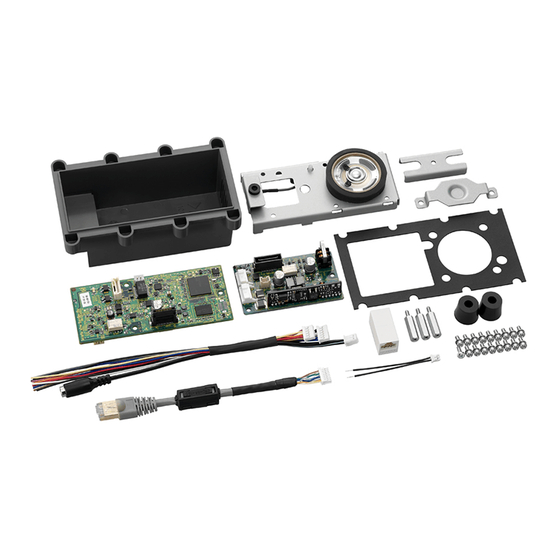
IP DOOR STATION BOARD
CAUTION
Use the specified AC adapter in combination.
Failure to do so may cause a fire.
1. GENERAL DESCRIPTION
The N-8640SB is an IP door station assembly kit consisting
of Main and Sub PC boards, cables, and mounting hardware
(excluding the operation panel) of the N-8640DS IP door station.
You can make the IP door station suitable for applications using
this kit in combination with the operation panel section to be
prepared separately.
Use the N-8000 Setting Software* to perform settings. Set up the
same items as those for the N-8640DS since the N-8640SB is
handled as the N-8640DS on the software.
Settings and operations are the same as those of the N-8640DS.
For details, read the descriptions about the N-8640DS in the
N-8000 series instruction manual*.
* Available for download on the TOA product data download site
(http://www.toa-products.com/international/).
2. COMPONENT PARTS
Main PC board ... 1
Sub PC board ... 1
Case ... 1
Case gasket ... 1
Sleeve ... 3
Cord bush ... 2
Call switch connection
harness ... 1
LAN connection cable ... 1
Machine screw M3 x 8
(with plain and spring washers) ... 17
Chassis (with speaker
and microphone) ... 1
Speaker bracket ... 1
Cord bush fixing bracket ... 1
LAN coupler ... 1
Power supply and external
input/output connection cable ... 1
Tapping screw 3 x 8 ... 1
INSTALLATION MANUAL
Be sure to ground the operation panel.
Follow the instructions below.
Doing otherwise may cause unit failure.
• The operation panel should be metallic.
• Install a frame ground terminal and ground the operation
panel. For details, refer to p. 4, "5. CONNECTIONS".
3. OPERATION PANEL DESIGN GUIDELINE
Note: The operation panel should be metallic, and grounded.
[Chassis and case mounting sleeve layout]
A
A
A
A
Microphone
mounting position
• A: Case mounting sleeve position
• B: Chassis mounting sleeve position
• Sleeve height: 11 mm (from the panel's rear surface)
• Sleeves should be metallic.
• Speaker opening size should be roughly 30% of the area of a
circle with the speaker's diameter.
• Microphone opening size should be roughly 70% or more of the
area of a circle with the microphone's diameter.
[Notes on the Call switch]
• Position the Call switch within the range shown above.
• The Call switch's height should be 20 mm or less from the op-
eration panel's rear surface.
• The Call switch should be of momentary type.
• When the above conditions could not be satisfied, provide an
external call switch using the external control input cables.
N-8640SB
Speaker mounting position
A
B
B
A
B
B
Switch position range
A
B
B
A
10.5
21
20
40
33.5
Unit: mm
67
133-06-304-6C
Advertisement

Related Manuals for Toa N-8640SB


Summary of Contents for Toa N-8640SB
- Page 1 Use the N-8000 Setting Software* to perform settings. Set up the same items as those for the N-8640DS since the N-8640SB is handled as the N-8640DS on the software. Settings and operations are the same as those of the N-8640DS.
- Page 2 4. ASSEMBLING Speaker bracket Step 1. Place the Case gasket onto the operation panel, then screw the chassis and speaker bracket to the operation panel. Machine screw (with plain and spring washers) M3 x 8 Step 2. Connect the connection cables and harness to the Main PC board, then secure the Main PC board to the chassis.
- Page 3 Step 5. Run the connection cables through the case’s cable [Dimensional diagram for the completed assembly] entry holes, then make cable connections. Unit: mm 5-1. Run the LAN connection cable through the case’s cable entry hole on your left, then connect it to the LAN connector on the Main PC board.
- Page 4 5. CONNECTIONS N-8640SB Be sure to ground the N-8640SB's frame ground terminal. Also ground the electrical box if used. Ext. connection cables Color Specifications Connected device Reference Frame Control OUT 1 ground Open collector OUT Control OUT 2 An indicator or other...
Need help?
Do you have a question about the N-8640SB and is the answer not in the manual?
Questions and answers