
Related Manuals for Emerson Machinery Health PR 9350


Summary of Contents for Emerson Machinery Health PR 9350
- Page 1 Operation Manual MHM-97864 NC: 6110-00125 04.06.2014 Rev.: 1.007 Machinery Health™ Sensor PR 9350 / K 20 315, Linear Displacement Transducer...
-
Page 2: Table Of Contents
Table of Contents Operation Manual 04.06.2014 NC: 6110-00125 Table of Contents Chapter 1: General ........Hints for using this manual . -
Page 3: Chapter 1: General
General Operation Manual 04.06.2014 NC: 6110-00125 Chapter 1: General Hints for using this manual This operating manual contains information on the correct use of the sensor PR 9350 and the set K 20 315. For the correct and safe use of the device, this operating manual must be read completely before starting the installation and operation. -
Page 4: Liability And Guarantee
If repair or calibration of a PR 9350 or K 20 315 is required, it must be sent to Emerson. Attach a non-detachable tag bearing customer name and defect observed to the sensor respectively set. -
Page 5: Disposal Of The Device
Jöbkesweg 3 D‐48599 Gronau Germany Phone: (+49) 02562 709‐0 Fax: (+49) 02562 709‐256 email: mmssupport.epro@emerson.com All rights reserved. Reproduction or digital use in any form and duplication are not permitted without written authority from epro GmbH part of Emerson Process Management. - Page 6 Operation Manual General NC: 6110-00125 04.06.2014 Copyright information...
-
Page 7: Chapter 2: Safety Instructions
Safety Instructions Operation Manual 04.06.2014 NC: 6110-00125 Chapter 2: Safety Instructions The device has left the factory in a faultless condition in regards to safety regulations. To preserve this condition and to ensure a safe operation, all instructions in this manual must be observed carefully. -
Page 8: Owner's Responsibility
Operation Manual Safety Instructions NC: 6110-00125 04.06.2014 Owner's responsibility If there is a reason to suspect, that hazard-free operation and thus adequate machine protection is no longer possible, the device must be taken out of operation and safeguarded from unintentional operation. This is the case •... -
Page 9: Chapter 3: Application & Design
Application & Design Operation Manual 04.06.2014 NC: 6110-00125 Chapter 3: Application & Design Application The inductive transducers PR 9350 or the set K 20 315 serve the measurement of static and dynamic displacements and - in connection with carrier frequency measuring bridges - of physical quantities (tensile and compressive forces, pressure of gases and liquids, thickness of materials, transverse moments) which may in any way be converted to linear movements by using relevant accessories. -
Page 10: Design
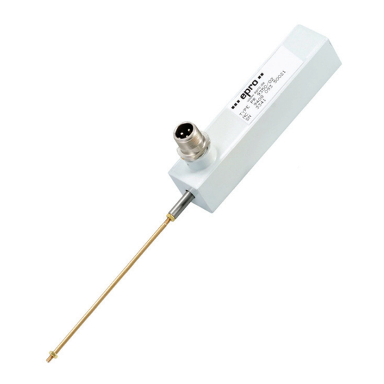
Operation Manual Application & Design NC: 6110-00125 04.06.2014 Design The following picture shows the sensor PR 9350/02 with a ±25mm measuring range. The sen sor housing is hermetically encapsulated and equipped with a 3-pole Cannon connector. The tracing pin has a M3 thread at the tip for mechanical connection to the measuring object. Figure 1 Sensor PR 9350 3-pole connector... - Page 11 Application & Design Operation Manual 04.06.2014 NC: 6110-00125 Figure 2 Shows the set K 20 315/02 with two meters armed sensor cable and Harting connection. Figure 2 Set K 20 315 Sensor cable with protection tube and Harting connector and socked 3 pole connector Housing with integrated sensor PR 9350/02 Application...
- Page 12 Operation Manual Application & Design NC: 6110-00125 04.06.2014 Application...
-
Page 13: Chapter 4: Mounting & Installation
Mounting & Installation Operation Manual 04.06.2014 NC: 6110-00125 Chapter 4: Mounting & Installation PR 9350 For mounting, the sensor PR 9350 is equipped with fixing holes with an internal M4 thread. The following Figure 3 and Table 1 shows the dimension of the single sensor type and the position of the fixing holes. -
Page 14: K 20 315
Operation Manual Mounting & Installation NC: 6110-00125 04.06.2014 K 20 315 Four mounting holes are available for mounting the K 20 315. Figure 4 and Table 2 show the position and dimension of this mounting holes. The tracing pin of the PR 9350 is connected to the movable part of the K 20 315. -
Page 15: Connection Of Pr 9350 And K 20 315
Mounting & Installation Operation Manual 04.06.2014 NC: 6110-00125 Connection of PR 9350 and K 20 315 Figure 5 shows the pin assignment of the 3-pole connector. Figure 5 Connection diagram Center tapped winding Ferromagnetic measuring element Figure 6 shows the pin assignment of the Harting connector of set K 20 315. The version K 20 315/03-S has open cable ends. -
Page 16: Commissioning
Operation Manual Mounting & Installation NC: 6110-00125 04.06.2014 Commissioning The manuals of the protection card A6410 respectively of the transmitter MMS 3410 contain further information regarding commissioning and installation of PR 9350 sensors and the set K 20 315. Commissioning... -
Page 17: Chapter 5: Function Check
Function check Operation Manual 04.06.2014 NC: 6110-00125 Chapter 5: Function check The PR 9350 sensor can be checked by measuring the internal sensor resistance at the connec tion terminals of the sensor (for pin assignment see Figure 5). This resistance is an indicator for sensor problems. - Page 18 Operation Manual Function check NC: 6110-00125 04.06.2014 Function check...
-
Page 19: Chapter 6: Technical Data
Technical Data Operation Manual 04.06.2014 NC: 6110-00125 Chapter 6: Technical Data Only specifications with tolerances or limit values are guaranteed. Data without tolerances or without error limits are for information only and not guaranteed. Technical modifications are subject to changes without notice. Sensitivity Diagonal voltage, bridge output per 1V supply voltage PR 9350/01... - Page 20 Operation Manual Technical Data NC: 6110-00125 04.06.2014 Accuracy Linearity error at 100% of measuring range 60% of measuring range ±1.5% ±1.0% PR 9350/01 ±3.5% ±0.5% PR 9350/02 ±2.5% ±0.5% PR 9350/04 ±2.0% ±0.5% PR 9350/06 ±2.0% ±0.2% PR 9350/08 ±1.5% ±0.2% PR 9350/12 Temperature influence...
- Page 21 Technical Data Operation Manual 04.06.2014 NC: 6110-00125 Nominal inductance (typical values A-C) PR 9350/08 Tracing pin … … in middle position 12 mH … maximum displacement 11 mH … min displacement 12 mH … driven out 6.3 mH PR 9350/12 Tracing pin …...
- Page 22 Operation Manual Technical Data NC: 6110-00125 04.06.2014 Mechanical design Dimensions for PR 9350/.. see chapter 4.1 for K 20 315/.. see chapter 4.2 K 20 315/.., spring force on /02; /03 and /03-S: max. 3.5 Nm measuring object /10 and /11: max.
- Page 23 Technical Data Operation Manual 04.06.2014 NC: 6110-00125 Included accessories PR 9350/.. Connector Cannon CA06COME10SL3S44 ITT Can Tracing pin (solenoid plunger) with M3 threaded rod K 20 315/02 and /10 2m connection cable with cannon plug CA06COME10SL3S44 ITT Can Tracing pin (solenoid plunger) with M3 threaded rod Metal protection tube and Harting−...
-
Page 24: Chapter 7: Om Revision List
Operation Manual OM Revision List NC: 6110-00125 04.06.2014 Chapter 7: OM Revision List Table 4 Revision List Version Date Changes / Remarks 1.000 02.09.2013 Initial Version 1.001 28.10.2013 Ticket 3404 1.002 12.11.2013 Update of technical data 1.003 14.11.2013 Update environmental conditions 1.004 06.01.2014 Change of technical data...
Need help?
Do you have a question about the Machinery Health PR 9350 and is the answer not in the manual?
Questions and answers