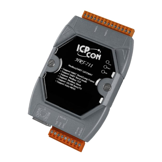
ICP DAS USA HRT-711 User Manual
Hide thumbs
Also See for HRT-711:
- User manual (97 pages) ,
- User manual (54 pages) ,
- Quick start manual (9 pages)
Summary of Contents for ICP DAS USA HRT-711
- Page 1 User Manual Version 1.12 2022/04/19 HRT-711 Written by Edward Fang Edited by Julia Wang...
-
Page 2: Table Of Contents
4.2.2 Input Data Area-Module State Data ..............22 4.2.3 Input Data Area-Default CMD 0 Data ..............24 4.2.4 Input Data Area-Default CMD 3 Normal Format Data .......... 24 HRT-711 User Manual Version 1.12 Page: Copyright © 2017 ICP DAS Co., Ltd. All Rights Reserved... - Page 3 Q01 : How to add HART devices to HRT-711 ? ..............53 Q02 : How to make sure that HRT-711 gets the HART device data correctly ? ....58 Q03 : How to map HART device CMD(3) data directly to SCADA or HMI ? ...... 61 Q04 : How to update the firmware of HRT-711 ? ...............
- Page 4 Q26:How to use the In_Offset field of the UserCMD ? ..........121 Q27:How to use “Listen Only” function to get HART data? ........... 126 Q28:I can't set it through RS-232, and I want to set HRT-711 through Ethernet. How can i do? ........................131 Q29:If I want to do Modbus TCP communication to port 502 via Ethernet, what is the...
- Page 5 Contact us If you encounter any problems while operating this device, feel free to contact us via mail at: service@icpdas.com . We guarantee to respond within 2 working days. HRT-711 User Manual Version 1.12 Page: Copyright © 2017 ICP DAS Co., Ltd. All Rights Reserved...
-
Page 6: Introduction
Modbus and HART are two kinds of famous protocols and used wildly in the fields of factory and process automation. The HRT-711 module is a Modbus/TCP and Modbus/UDP to HART gateway. By using this module, users can integrate their HART devices into Modbus network easily. The below figure 1 shows an application example for the HRT-711 module. -
Page 7: Features
Support On-line Replacement of HART Devices Support Acquire Long Frame Address Automatically Provide LED indicators Built-in Watchdog DIN-Rail or Wall Mounting HRT-711 User Manual Version 1.12 Page: Copyright © 2017 ICP DAS Co., Ltd. All Rights Reserved E-mail: service@icpdas.com... -
Page 8: Specification
Humidity: 5 ~ 95% RH, non-condensing Module 3 x LED indicators ETH LED Network Status HART LED HART Status ERR LED Error HRT-711 User Manual Version 1.12 Page: Copyright © 2017 ICP DAS Co., Ltd. All Rights Reserved E-mail: service@icpdas.com... -
Page 9: Hardware
2. Hardware 2.1 Block Diagram HRT-711 User Manual Version 1.12 Page: Copyright © 2017 ICP DAS Co., Ltd. All Rights Reserved E-mail: service@icpdas.com... -
Page 10: Pin Assignment
GND of Power Supply Transmit Data of RS-232 Configuration Receive Data of RS-232 GND of RS-232 Modbus/TCP Ethernet RJ45 connector for Modbus/TCP and Modbus/UDP Modbus/UDP HRT-711 User Manual Version 1.12 Page: Copyright © 2017 ICP DAS Co., Ltd. All Rights Reserved E-mail: service@icpdas.com... -
Page 11: Wiring
In this section, this user’s manual will introduce the wiring for each interface. 2.3.1 RS-232 The RS-232 port of HRT-711 uses a 3-wire communication interface. It needs a unique cable, CA-0910, to wire from screwed terminal block to D-Sub 9pin connector. Users can choose between using CA-0910 for RS-232 wiring or directly connecting to D-Sub. -
Page 12: Hart
The wiring of HART bus can be devided into two types. One is loop power (Passive Loop), and the other is external power (Active Loop). The following figures show the wiring for the HART bus. HRT-711 User Manual Version 1.12 Page:... -
Page 13: Ethernet
2.3.3 Ethernet The wiring for Ethernet is directly connecting your RJ-45 Ethernet cable to the RJ-45 port on the HRT-711. HRT-711 User Manual Version 1.12 Page: Copyright © 2017 ICP DAS Co., Ltd. All Rights Reserved E-mail: service@icpdas.com... -
Page 14: Led Indicators
2.4 LED Indicators The HRT-711 provides three LED indicators to indicate the module status. The descriptions are shown as follow. Status Description Blink every 0.2 second:Receiving Ethernet packet Blink Blink every 3 second:The network function is normal Ethernet Error Blink every 1 second:... -
Page 15: Dip Switch
On the init side, the module can be configured through Utility. On the normal side, the module is a gateway between HART and Modbus/TCP, Modbus/UDP protocol. Users have to power cycle the module when switch to different mode. HRT-711 User Manual Version 1.12 Page:... -
Page 16: Jumpers
JP4 without jumper connected, it will disconnect the resistor from HART bus. By default, the pin1&2 of JP4 is closed. Please refer to section 2.3.2. 2.7 Mounting HRT-711 User Manual Version 1.12 Page: Copyright © 2017 ICP DAS Co., Ltd. All Rights Reserved... -
Page 17: Hart Introduction
- 1,200 Hz and 2,200 Hz representing bits 1 and 0, respectively. Sine waves of these two frequencies are superimposed on the direct current (dc) analog signal cables to provide simultaneous analog and digital communications. HRT-711 User Manual Version 1.12 Page:... -
Page 18: Topology
7 HART devices simultaneously. If the HART devices in multi-drop mode are more than 7, then users need to disconnect the built-in resistor in HRT-711 (prevent to burn down) and use an external 250 Ohm resistor with 1W. - Page 19 HRT-711 User Manual Version 1.12 Page: Copyright © 2017 ICP DAS Co., Ltd. All Rights Reserved E-mail: service@icpdas.com...
-
Page 20: Hart Frame
This byte is used for error status when Bit7 is 1. The status bits are shown as follow Bit7 Bit6 Bit5 Bit4 Bit3 Bit2 Bit1 Bit0 HRT-711 User Manual Version 1.12 Page: Copyright © 2017 ICP DAS Co., Ltd. All Rights Reserved E-mail: service@icpdas.com...


Need help?
Do you have a question about the HRT-711 and is the answer not in the manual?
Questions and answers