Armstrong 4312 Installation And Operating Instructions Manual
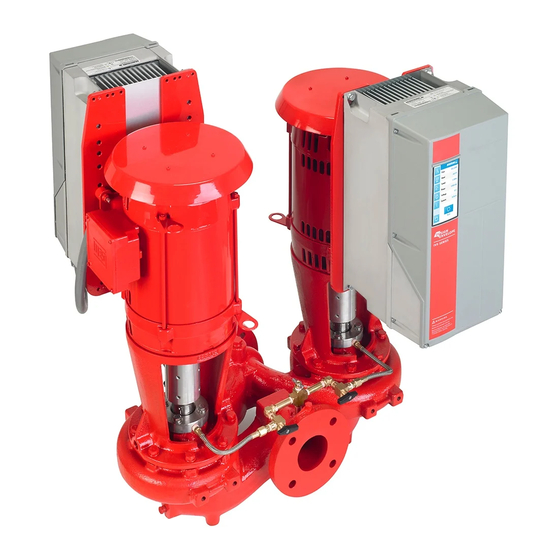
Design envelope vertical in-line twin pumping unit
Hide thumbs
Also See for 4312:
- Installation and operating instructions manual (42 pages) ,
- Quick installation manual (4 pages) ,
- Quick installation manual (4 pages)

Related Manuals for Armstrong 4312


Summary of Contents for Armstrong 4312
- Page 1 Design Envelope 4312 & 4392 Vertical In-line Twin Pumping Unit Installation and operating instructions File No: 94.84 Date: february 03, 2016 Supersedes: 94.84 Date: april 15, 2015...
-
Page 3: Table Of Contents
1.0 Uncrating 5.4 Programming 1.1 Handling Design Envelope 5.4.1 Parameter selection 4312 & 4392 units 5.4.2 Changing data 2.0 Installation Sensoreless operation 2.1 Mechanical installation 6.1 Default operating mode – 2.1.1 Location quadratic pressure control 2.1.2 Storage 6.1.1 Settings for quadratic (control curve) 2.1.3 Installation... -
Page 4: Uncrating
2.1.3 installation The most important consideration when installing a Design Envelope 4312 and 4392 pumping unit is to make sure the pump is free to ‘float’ with expansion and contraction of the piping. Recommended arrangements are: •... -
Page 5: Pump Piping - General
Care must be taken in the suction line layout and installation, as it is usually the major source of All Design Envelope 4312 pumps contain a tapped hole in the concern in centrifugal pump applications. motor bracket above the discharge flange for draining the well. -
Page 6: General Care
Mechanical seals require no special attention. The mechanical giving special attention to the following: seal is flushed from discharge of the pump casing on 4312 and • Keep unit clean. towards the suction on 4392. Seal environmental controls, installed in flush lines, such as filters and separators, will pro- •... -
Page 7: System Cleanliness
Do not run the pump unless properly filled with water as the fig. 2.1 Hanger supported pipe mounted mechanical seals need a film of liquid between the faces for proper operation. (For 4312 see file 43d.88 and for 4392 see file 43d.81 for mechanical seal replacement instructions) 2.1.9 system cleanliness Before starting the pump the system must be thoroughly cleaned, flushed and drained and replenished with clean liquid. - Page 8 Neoprene Drain connection finished floor isolation pad fig . 2 . 8 Tapped collection well on Design Envelope 4312 fig . 2 .5 Floor saddle support Design Envelope 4312 seal leaks or condensate drain hole. Plumb to drain for area cleanliness fig .
-
Page 9: Enclosure Rating
The standard enclosure rating for Design Envelope on-board inverter has not been grounded. 4312 and 4392 integrated controls is nema/ul type 12. Since the leakage current is >3.5ma (approx 4-20ma), If the pump is to be installed in a wet or dusty... -
Page 10: Supply Voltage
38 0 -48 0V/ 5 25- 6 0 0V - 10hp and below) The inverter must be protected against short-circuit to avoid electrical or fire hazard. Armstrong recommends using the fuses detailed in the separate ivs102 Operating Instructions to pro- tect service personnel or other equipment in case of an internal failure in the unit. -
Page 11: Relay Connections
Design Envelope 4312 and 4392 vertical inline insta l l a t io n & o per at ing i n str uct io n s twin pumping unit with integrated controls fig . 4b Mains and grounding connections for c1 and The illustrations in figures 6, 7 and 8 identify the location of the c2 units (200-240V –... -
Page 12: Electrical Installation And Control Connections
& Design Envelope 4312 and 4392 vertical inline operati ng instruction s twin pumping unit with integrated controls 4 .8 electrical installation and control connections fig . 8 Diagram showing all electrical connections *Note: terminal 37 is not available on Design Envelope pumps... -
Page 13: Access To Terminals
Design Envelope 4312 and 4392 vertical inline insta l l a t io n & o per at ing i n str uct io n s twin pumping unit with integrated controls 4 .8.1 access to terminals Control terminal functions and factory settings are as follows: terminal no. -
Page 14: Connection Examples
& Design Envelope 4312 and 4392 vertical inline operati ng instruction s twin pumping unit with integrated controls 4 .8.3 connection examples ii closed loop – with sensor feedback Design Envelope pumps can be configured in four main ways: To control the pump based on a 4-20mA feedback signal from a sensor use the following connection. -
Page 15: Remote Lcp Keypad Wiring
Design Envelope 4312 and 4392 vertical inline insta l l a t io n & o per at ing i n str uct io n s twin pumping unit with integrated controls iii constant curve mode – potentiometer iv.i constant curve mode - bms signal... -
Page 16: Programming, Monitoring
& Design Envelope 4312 and 4392 vertical inline operati ng instruction s twin pumping unit with integrated controls 5 .0 progr amming, monitoring The display is divided into three sections: and diagnostics Top section (a) shows the status when in status mode or up... -
Page 17: Indicator Lights (Leds)
Design Envelope 4312 and 4392 vertical inline insta l l a t io n & o per at ing i n str uct io n s twin pumping unit with integrated controls Display Contrast Adjustment Use Status for selecting the mode of display or for changing... -
Page 18: Programming
& Design Envelope 4312 and 4392 vertical inline operati ng instruction s twin pumping unit with integrated controls All parameters can be changed in the Main Menu. However, Hand On depending on the choice of configuration ( Par. 1-00 Configura- Enables control of the pump via the glcp. -
Page 19: Changing Data
Design Envelope 4312 and 4392 vertical inline insta l l a t io n & o per at ing i n str uct io n s twin pumping unit with integrated controls 5 . 4 . 2 changing data The procedure for changing data depends on whether the selected parameter represents a numerical data value or a text value. -
Page 20: Default Operating Mode - Quadratic Pressure Control
& Design Envelope 4312 and 4392 vertical inline operati ng instruction s twin pumping unit with integrated controls 6.1 default oper ating mode — 6.1.1 settings for quadr atic quadr atic pressure control (control curve) pressure control The default control mode for Design Envelope pumps is ‘Qua-... -
Page 21: Constant Pressure Control
Design Envelope 4312 and 4392 vertical inline insta l l a t io n & o per at ing i n str uct io n s twin pumping unit with integrated controls 6.3 changing control modes fig . 11 curve approximation set tings h (head) 6.3 .1 change to external sensor control... -
Page 22: Change To Sensorless Control
& Design Envelope 4312 and 4392 vertical inline operati ng instruction s twin pumping unit with integrated controls 6 The drive on/off status can be read as a dry contact be- energize and the dry contacts will close. When the system... -
Page 23: Multiple Sensor Control
Design Envelope 4312 and 4392 vertical inline insta l l a t io n & o per at ing i n str uct io n s twin pumping unit with integrated controls Wiring 6. 4 . 2 multiple sensor control Prior to wiring, set the analog input switches to 0-10V. - Page 24 & Design Envelope 4312 and 4392 vertical inline operati ng instruction s twin pumping unit with integrated controls ivs102 controller programming parameter value parameter comments number setup 1 Configure the parameters for both drives as indicated by the tables below.
-
Page 25: Motor Pre-Heat Application
Design Envelope 4312 and 4392 vertical inline insta l l a t io n & o per at ing i n str uct io n s twin pumping unit with integrated controls 6. 4 .3 motor pre-heat application Sensor method... - Page 26 & Design Envelope 4312 and 4392 vertical inline operati ng instruction s twin pumping unit with integrated controls Wiring Sensor method Connect the digital input to Terminal 19. Power can be taken from Terminal 12 or 13.
-
Page 27: Start Standby By Falling Sensor Reading
Design Envelope 4312 and 4392 vertical inline insta l l a t io n & o per at ing i n str uct io n s twin pumping unit with integrated controls Sensor method ivs 102 Controller Programming 1 When the sensor has detected moisture, the setup will be Configure the parameters as indicated by the tables below. - Page 28 & Design Envelope 4312 and 4392 vertical inline operati ng instruction s twin pumping unit with integrated controls Site Requirements 2 Move switch s202 (beside terminal input 54) to on if the sensor signal is 4-20mA, or leave it off if it’s 0-10Vdc...
- Page 29 Design Envelope 4312 and 4392 vertical inline insta l l a t io n & o per at ing i n str uct io n s twin pumping unit with integrated controls parameter name value description Comparator Operand [13] Analog input ai54 If sensor input…...
-
Page 30: Start Standby By System Contact Opening
& Design Envelope 4312 and 4392 vertical inline operati ng instruction s twin pumping unit with integrated controls 6. 4 .5 start standby by system contact Personnel Requirements opening 1 Armstrong Tier 3 training or equivalent... - Page 31 Design Envelope 4312 and 4392 vertical inline insta l l a t io n & o per at ing i n str uct io n s twin pumping unit with integrated controls parameter name value description Comparator Operand [131] di-19 If the contact is…...
-
Page 32: Warnings And Alarms
& Design Envelope 4312 and 4392 vertical inline operati ng instruction s twin pumping unit with integrated controls 7.0 warnings and alarms wa r n i n g /a l a r m 3 , No motor: No motor has been connected to the output of the inverter. - Page 33 Design Envelope 4312 and 4392 vertical inline insta l l a t io n & o per at ing i n str uct io n s twin pumping unit with integrated controls wa r n i n g /a l a r m 13, Over Current: wa r n i n g /a l a r m 27, Brake chopper fault: The inverter peak current limit (approx.
- Page 34 & Design Envelope 4312 and 4392 vertical inline operati ng instruction s twin pumping unit with integrated controls wa r n i n g 41, Overload of Digital Output wa r n i n g /a l a r m 58, ama internal fault: Terminal 29: Contact your Armstrong supplier.
-
Page 35: Acoustic Noise And Vibration
Design Envelope 4312 and 4392 vertical inline insta l l a t io n & o per at ing i n str uct io n s twin pumping unit with integrated controls a l a r m 92, No Flow: a l a r m 250, New Spare Part: A no load situation has been detected for the system. - Page 36 & Design Envelope 4312 and 4392 vertical inline operati ng instruction s twin pumping unit with integrated controls table 1 Alarm/warning code list description warning alarm alarm par ameter reference / trip / trip lock 10 volts low Live zero error Par.
- Page 37 Design Envelope 4312 and 4392 vertical inline insta l l a t io n & o per at ing i n str uct io n s twin pumping unit with integrated controls description warning alarm/ trip alarm/ trip par ameter reference...
- Page 38 & Design Envelope 4312 and 4392 vertical inline o p era t ing i nstruct ion s twin pumping unit with integrated controls table 2 ivs 102 parameter settings par. name setup 1...
- Page 39 Design Envelope 4312 and 4392 vertical inline insta l l a t io n & o per at ing i n str uct io n s twin pumping unit with integrated controls par. name setup 1 setup 2 setup 3...
- Page 40 t o r o n t o 23 bertrand avenue toronto, ontario canada m1l 2p3 +1 416 755 2291 b u f f a l o 93 east avenue north tonawanda, new york u.s.a. 14120 -6594 +1 716 693 8813 b i r m i n g h a m heywood wharf, mucklow hill halesowen, west midlands...
Need help?
Do you have a question about the 4312 and is the answer not in the manual?
Questions and answers