
Related Manuals for Armstrong 4302 IVS Series


Summary of Contents for Armstrong 4302 IVS Series
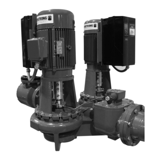
- Page 1 FILE NO: 94.82L DATE: Aug. 24, 2009 SUPERSEDES: New DATE: INSTALLATION AND OPERATING INSTRUCTIONS Series 4302 IVS Vertical In-Line Pumping Unit with Integrated Controls Product shown with coupling guards removed...
-
Page 2: Installation
1.0 UNCRATING For long term storage, the pump must be placed in a Armstrong dualARM Design Envelope 4302 IVS in-line vertical position in a dry environment. pumps are thoroughly inspected before shipment to Internal rusting can be prevented by removing the ... -
Page 3: Operation
“cracked” or essential when handling liquids above 120°F (49°C). open slightly at start up to help eliminate trapped air. Armstrong suction guides may be used in place of When stopping the pump: Close the discharge valve the straight pipe run and in line strainer. -
Page 4: Warranty
WARRANTY AUTOMATIC FLAPPER OPERATION In the flapper mode the two halves of the discharge valve Refer to Armstrong General Terms and Warranty are free to pivot independently under normal operating sheet. Contact your local Armstrong representative for conditions. The locking handle (3) should be secured with full information. - Page 5 Rotate discharge valve shaft (16) towards the pump NOTE to be isolated. The orientation of the shaft is indicated THE LOCKING HANDLE (3) SHOULD ONLY BE by the center pin on the locking arm (4). ROTATED TOWARDS THE PUMP STOPPED FOR Raise the locking handle (3) so that the cam on the SERVICE.
-
Page 6: Suction Valve
VALVE ILLUSTRATION (3”, 4” and 6”) This pump suction is now closed. (Locked when This pump discharge is now closed. (Locked when handle is elevated and secured). handle is elevated and secured). SUCTION VALVE DISCHARGE VALVE Normal Operation Normal Operation... - Page 7 VALVE ILLUSTRATION (8”) This pump suction is now closed. (Locked when This pump discharge is now closed. (Locked when handle is elevated and secured). handle is elevated and secured). SUCTION VALVE DISCHARGE VALVE Normal Operation Normal Operation...
- Page 8 Fig. 2.2 Pipe mounted supported at ceiling Fig. 2.1 Hanger supported pipe mounted Fig. 2.4 With additional pipe supports Fig. 2.3 Discharge elbow for minimum footprint Fig. 2.5 Floor saddle support Fig. 2.6 Additional floor support Series 4302 IVS seal leaks or condensate drain hole.
-
Page 9: Electrical Installation
Suitable for protecting equipment with a direct current INTEGRATED CONTROLS content (DC) in the fault current (3-phase bridge recti- POWER RATINGS 0.55 to 7.5kW fier) Suitable for power-up with short charging current to earth 3.1 ENCLOSURE RATING Suitable for a high leakage current The standard enclosure rating for IVS Sensor- less pumps is IP55. -
Page 10: Mains Supply Connection
This switch is only used for serial communications to BMS and should otherwise be left in the off position. Figure 2. Inverter Terminal Arrangement vi. Remove the middle gland plug and feed the control 4.8 MAINS SUPPLY CONNECTION cable through the hole (see the section on control i. -
Page 11: Connection Examples
X102 TERMINALS - PUMP RUNNING X101 TERMINALS - CONTROL TERMINALS The X102 terminals provide a relay changeover contact The X101 terminals are used for analogue and digital for identification of pump running. signals that will determine the operation of the pump (see the section on Control Modes). - Page 12 ii. FULL SPEED OVERIDE - CONNECTION DETAILS Running It may be required to run the pump at full speed without Output automatic speed control (e.g. during system commission- ing). This can be achieved without programming changes by making the control connections shown below. Running Output Fault...
-
Page 13: Programming, Monitoring And Di- Agnostics
All data is indicated by means of a 4-line alphanumeric PROGRAMMING, MONITORING AND DI- display, which in normal operation is able show 4 AGNOSTICS measurements and 3 operating conditions continuously. A key pad tool (LCP) is available for IVS Sensorless During programming, all the information required for Pumps as an option. -
Page 14: Control Keys
[STOP / RESET] is used for stopping or for 5.1.3 CONTROL KEYS The control keys are divided into functions. This means resetting the pump after a drop-out (trip). Can be that the keys between display and indicator LEDs are selected via parameter 014 to be active or used for parameter Setup, including choice of display inactive. -
Page 15: Quick Menu
The table below gives the units linked to the variables in the first and second line of the display (see parameter 009). In this state, data values for four operating values are shown at the same time, giving the related unit, cf. table. Operating variable: Unit: In the example, Reference, Torque, Current and... - Page 16 Parameter Groups In the Menu mode the parameters are divided into groups. Selection of parameter group is effected by means of the [<>] keys. The following parameter groups are accessible: Group no. Parameter group: Operation & Display Load & Motor References &...
- Page 17 Menu Structure...
-
Page 18: Sensorless Operation
point. The maximum controllable head (Head Qmax) is SENSORLESS OPERATION the head developed when the pump reaches full speed Sensorless control is an innovative concept in glanded and is calculated by the other two head settings. circulating pumps. Pump performance and characteristic curves for ten different speeds are embedded in the memory of the speed controller during manufacture. -
Page 19: Setting Parameters For Proportional Pressure Control
6.3.1 SETTING PARAMETERS FOR PROPORTIONAL Group 1 – Load and Motor. PRESSURE CONTROL Configuration – Parameter 100 Parameter 716 - Enter the head (kPa) at design flow. Sets the configuration under which the inverter is con- Parameter 717 - Enter the design flow (l/s). trolled. - Page 20 ‘No Flow’ conditions. Set to 100% if a constant For further information on serial communication, con- head is required across the full flow range. tact Armstrong. Group 6 – Technical Functions. Power Consumption – Parameter 708 Normally set to 0 option correction factor that mainly af- Operating Hours –...
- Page 21 ° Temperature Rise Rated – Parameter 710 Slip 100 C – Parameter 713 ° Normally set to 80 C. This specifies the estimated differ- Normally set to 0%. This specifies the estimated change ence in rotor temperature from idle running conditions to in motor slip at the temperature 100vC above the idle maximum loaded conditions.
- Page 22 Recommended Parameter Settings Description Parameter Sensorless Open Loop Closed Loop Language English English English Local/Remote Control Local Remote Remote Local Reference 000.000 000.000 000.000 Active Setup Multi Setup Setup 1 Setup 1 Programming Setup Active Setup Active Setup Active Setup Copying of Setups No Copy No Copy...
- Page 23 Recommended Parameter Settings Description Sensorless Open Loop Closed Loop Parameter Time Out 10 Seconds 10 Seconds 10 Seconds Function After Time Out Stop and Trip X102 Relay Function Running Running Running Pulse Reference/Feedback Max Frequency 5000Hz 5000Hz 5000Hz Terminal 1, Analogue Input Current No Operation Feedback Feedback...
- Page 24 the fault must be corrected. Reconnect the mains WARNINGS AND ALARMS supply and reset (auto-reset by default) the pump There are two means of notification of warnings and before starting. Wherever a cross is placed under both alarms on an IVS Sensorless pump. The keypad tool Warning and Alarm, this can mean that a warning (LCP) will display alarm information and in addition to this precedes the alarm.
- Page 25 * 760V in 5 sec. or 800V immediately. The voltages stated are the intermediate circuit voltage ALARM: 37 of the inverter. Internal error (INTERNAL ERROR): An error has occurred in the system. Contact Armstrong Holden Brooke Pullen. ALARM 11 Motor thermistor (MOTOR THERMISTOR): 8.1 INTERNAL LED DESCRIPTIONS If a thermistor is mounted and parameter 128 is set to The LED’s (shown in figure 2, page 3) can be used to...
- Page 26 Yes - been pressed? signal from Display Flashing Press the key pad start key Does the display show an alarm? See the alarm descriptions on page 17 / 18 Contact Armstrong Holden Brooke Pullen service department...
- Page 27 Check remote 301 flashing reference slowly? signal from Local Stop - A keypad is required to start the unit Is red LED 300 lit? There is a fault - use a keypad to diagnose Contact Armstrong Holden Brooke Pullen service department...
- Page 28 Never use ELCB relays that are not suitable The inverter must be protected against short-circuit to for DC fault currents (type A). avoid electrical or fire hazard. Armstrong recommends If ELCB relays are used, they must be: using the fuses detailed in the separate IVS102 Operating Instructions to protect service personnel or other equip- ...
-
Page 29: Relay Connections
4.6 EARTHING AND IT MAINS The earth connection cable cross section must be at least 10 mm2 or 2 rated mains wires ter- minated separately according to EN 50178 or IEC 61800-5-1 unless national regulations specify differently. Always comply with national and local regulations on cable cross sections. -
Page 30: Electrical Installation And Control Connections
The illustrations in figures 6 and 7 identify the location of the relays within specific inverter sizes: Figure 7. Relay Connection Terminals for Figure 6. Relay Connection Terminals for Units 37kW to 55kW Units 11kW to 30kW 4.8 ELECTRICAL INSTALLATION AND CONTROL CONNECTIONS *Note:Terminal 37 is not available on IVS Sensorless pumps Figure 8. -
Page 31: Access To Terminals
Control terminal functions and factory settings are as fol- 4.8.1 ACCESS TO TERMINALS lows: Terminal Type / Desc Factory Setting Relay 1 Running 1,2,3 Relay 2 Alarm 4,5,6 Supply +24V DC Supply +24V DC Digital Input Start Digital Input Pump Operating Mode Common Digital Input Low Water Interlock... - Page 32 iii. CONSTANT CURVE MODE - BMS SPEED CON- 4.8.3 CONNECTION EXAMPLES TROL There are many ways that an IVS Sensorless pump can Where the Building Management System is to be used for be configured. The following is some examples of the speed control it is necessary to disable sensorless control most common control configurations.
-
Page 33: Glcp Functions And Operation
Operating variables with different formatting are shown in PROGRAMMING, MONITORING AND DI- each status screen - see below. AGNOSTICS IVS Sensorless pumps with power ratings 11.0kW and Status display I: above incorporate an integrated graphical local control This read-out state is standard after start-up or initialisa- panel (GLCP). - Page 34 Navigation Keys 5.3 CONTROL KEYS The four navigation arrows are used to navigate between Menu keys the different choices available in [Quick Menu], [Main The menu keys are divided into functions. The keys below the display and indicator lamps are used for parameter set-up, including choice of display indication during nor- mal operation.
-
Page 35: Parameter Selection
5.4 PROGRAMMING Changing a Text Value Select the Main Menu mode by pressing the [Main Menu] If the selected parameter is a text value, change the text key. The below read-out appears on the display. The mid- value by means of the [▲] [▼] navigation keys. dle and bottom sections on the display show a list of pa- The up key increases the value, and the down key de- rameter groups which can be chosen by toggling the up... -
Page 36: Default Operating Mode - Quadratic Pressure Control
curves for ten different speeds are embedded in the memory of the speed controller during manufacture. This data includes power, pressure and flow across the flow range of the pump. During operation, the power and speed of the pump are monitored, enabling the controller to establish the hydraulic performance and position in the pumps head-flow characteristic. -
Page 37: Warnings And Alarms
The intermediate circuit voltage (DC) is below the under WARNINGS AND ALARMS voltage limit of the control system. The inverter is still ac- A warning or an alarm is signalled by the relevant LED on tive. the front of the inverter and indicated by a code on the display. - Page 38 Table 1. Alarm/Warning Code List...
- Page 39 WARNING/ALARM 10, Motor ETR over temperature: WARNING 25, Brake resistor short-circuited: According to the electronic thermal protection (ETR), the The brake resistor is monitored during operation. If it motor is too hot. You can choose if you want the inverter short-circuits, the brake function is disconnected and the to give a warning or an alarm when the counter reaches warning appears.
- Page 40 The external 24 V DC backup power supply may be over- The heat sink temperature is measured as 0 °C. This loaded, otherwise contact your Armstrong supplier. could indicate that the temperature sensor is defective and thus the fan speed is increased to the maximum in case the power part or control card is very hot.
-
Page 41: Acoustic Noise And Vibration
Canada, M1L 2P3 U.S.A. 14120-6594 United Kingdom, M12 5JL T: 416-755-2291 T: 716-693-8813 T: +44 (0) 161 223 2223 F: 416-759-9101 F: 716-693-8970 F: +44 (0) 161 220 9660 © S.A. Armstrong Limited 2009 For Armstrong locations worldwide, please visit www.armstrongintegrated.com...
Need help?
Do you have a question about the 4302 IVS Series and is the answer not in the manual?
Questions and answers