Advertisement
Quick Links
Prepared (Subject resp)
Prepared (Subject resp)
jidgjian Grace Jiang
Approved (Document resp)
BMR46 series PoL Regulators
BMR46 series PoL Regulators
BMR46 series PoL Regulators
Approved (Document resp)
jidgjian Grace Jiang
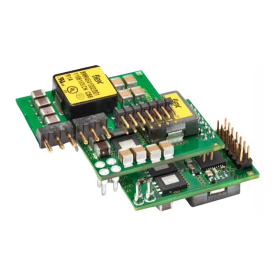
Input 4.5-14 V, Output up to 50 A / 165 W
Input 4.5-14 V, Output up to 50 A / 165 W
Input 4.5-14 V, Output up to 50 A / 165 W
Key Features
• Small package
30.85 x 20.0 x 8.2 mm (1.215 x 0.787 x 0.323 in)
SIP: 33.0 x 7.6 x 18.1 mm (1.30 x 0.30 x 0.713 in)
• 0.6 V - 3.3 V output voltage range
• High efficiency, typ. 97.2% at 5Vin, 3.3Vout half load
• Configuration and Monitoring via PMBus
• Dynamic Loop Compensation (DLC) & fast loop
transient response
• Synchonization & phase spreading
• Current sharing, Voltage Tracking & Voltage margining
• MTBF 14.2 Mh
General Characteristics
Fully regulated
For narrow board pitch applications (15 mm/0.6 in)
Non-Linear Response for reduction of decoupling cap.
Input under voltage shutdown
Over temperature protection
Output short-circuit &
Output over voltage
Remote control & Power Good
Voltage setting via pin-strap or PMBus
Configurable via Graphical User Interface
ISO 9001/14001 certified supplier
Highly automated manufacturing ensures quality
Contents
Absolute Maximum Ratings
Electrical Specification
40A/ 0.6-3.3V Through hole and Surface mount version
40A/ 0.6-3.3V Single in Line version (SIP)
50A/ 0.6-3.3V DLC, Through hole and Surface mount version
50A/ 0.6-3.3V DLC, Single in Line version (SIP)
50A/ 0.6-3.3V Single in Line version (SIP)
EMC Specification
Operating Information
Thermal Consideration
Connections
Mechanical Information
Soldering Information - Surface Mounting and Hole Mounting (Laydown version) ................................................... 74
Delivery Package Information
Soldering Information - Hole Mounting (SIP version)
Delivery Package Information (SIP version)
Product Qualification Specification
Checked
Checked
protection
(Laydown version)
INTERNAL USE ONLY
INTERNAL USE ONLY
PRODUCT SPECIFICATION
TABLE OF CONTENTS
No.
No.
1/1301-BMR 464 Uen
Technical Specification
Technical Specification
Technical Specification
BPOW 00201-00152 Uen
Date
Rev
1/28701-BMR 464 Rev.B
1/28701-BMR 464 Rev.B
1/28701-BMR 464 Rev.B
Date
Rev
7/4/2019
G
7/10/2009
PD1
© Flex
© Flex
© Flex
Safety Approvals
Design for Environment
Meets requirements in high-temperature
lead-free soldering processes.
............................................................. 2
............................................................. 2
............................................................. 3
............................................................. 4
BMR4640002, BMR4641002 ................ 5
BMR4642002 ...................................... 14
BMR4640008, BMR4641008 .............. 23
BMR4642008 ...................................... 32
BMR4642012 ...................................... 41
........................................................... 49
........................................................... 49
........................................................... 60
........................................................... 61
........................................................... 71
........................................................... 75
........................................................... 76
........................................................... 76
........................................................... 77
1 (4)
1 (1)
July 2019
July 2019
July 2019
Y
D
Advertisement

Subscribe to Our Youtube Channel
Related Manuals for Flex BMR464 Series


Summary of Contents for Flex BMR464 Series
-
Page 1: Table Of Contents
Input 4.5-14 V, Output up to 50 A / 165 W Input 4.5-14 V, Output up to 50 A / 165 W Input 4.5-14 V, Output up to 50 A / 165 W © Flex © Flex © Flex Key Features •... -
Page 2: Ordering Information
ο ο ο Configuration file ο Exemptions in the RoHS directive utilized in Flex products Packaging are found in the Statement of Compliance document. Options Description Flex fulfills and will continuously fulfill all its obligations under regulation (EC) No 1907/2006 concerning the... -
Page 3: Safety Specification
General information input source meets the requirements for ES1 according to IEC/EN/UL 62368-1. Flex Power DC/DC converters and DC/DC regulators are designed in accordance with the safety standards IEC 62368-1, EN 62368-1 and UL 62368-1 Audio/video, information and communication technology equipment -... - Page 4 1/28701-BMR 464 Rev.B July 2019 July 2019 Input 4.5-14 V, Output up to 50 A / 165 W Input 4.5-14 V, Output up to 50 A / 165 W © Flex © Flex Absolute Maximum Ratings Characteristics Unit Operating temperature (see Thermal Consideration section) °C...
-
Page 5: Bmr4640002, Bmr4641002
July 2019 July 2019 Input 4.5-14 V, Output up to 50 A / 165 W Input 4.5-14 V, Output up to 50 A / 165 W © Flex © Flex Electrical Specification BMR 464 0002, BMR 464 1002 = -30 to +95 °C, V = 4.5 to 14 V, V... - Page 6 1/28701-BMR 464 Rev.B 1/28701-BMR 464 Rev.B July 2019 July 2019 Input 4.5-14 V, Output up to 50 A / 165 W Input 4.5-14 V, Output up to 50 A / 165 W © Flex © Flex Characteristics Conditions Unit Default configuration:...
- Page 7 Reference BMR46 series PoL Regulators 1/28701-BMR 464 Rev.B July 2019 EAB/FJB/GM (Ksenia Harrisen) (MICRF) 2014-05-02 Input 4.5-14 V, Output up to 50 A / 165 W © Flex Characteristics Conditions Unit OCP threshold OCP threshold range PMBus configurable 0-48 Over Current...
- Page 8 Note 17: For steady state operation above 1.05 x 3.3 V, please contact your local Flex sales representative. Note 18: A minimum load current is not required if Low Power mode is used (monitoring disabled). Note 19: Please check with your local Flex Sales representative if you intend to adjust the frequency exceeds 320 KHz ±10%.
- Page 9 July 2019 July 2019 Input 4.5-14 V, Output up to 50 A / 165 W Input 4.5-14 V, Output up to 50 A / 165 W © Flex © Flex Typical Characteristics BMR 464 0002, BMR 464 1002 Efficiency and Power Dissipation Efficiency vs.
- Page 10 July 2019 July 2019 Input 4.5-14 V, Output up to 50 A / 165 W Input 4.5-14 V, Output up to 50 A / 165 W © Flex © Flex Typical Characteristics BMR 464 0002, BMR 464 1002 Load Transient Load Transient vs.
- Page 11 July 2019 July 2019 Input 4.5-14 V, Output up to 50 A / 165 W Input 4.5-14 V, Output up to 50 A / 165 W © Flex © Flex Typical Characteristics BMR 464 0002, BMR 464 1002 Output Current Characteristic Output Current Derating, V = 0.6 V...
- Page 12 1/28701-BMR 464 Rev.B July 2019 July 2019 Input 4.5-14 V, Output up to 50 A / 165 W Input 4.5-14 V, Output up to 50 A / 165 W © Flex © Flex ypical Chara acteristics R 464 0002, B...
- Page 13 July 2019 July 2019 Input 4.5-14 V, Output up to 50 A / 165 W Input 4.5-14 V, Output up to 50 A / 165 W © Flex © Flex Typical Characteristics BMR 464 0002, BMR 464 1002 Start-up and shut-down...
-
Page 14: Bmr4642002
July 2019 July 2019 Input 4.5-14 V, Output up to 50 A / 165 W Input 4.5-14 V, Output up to 50 A / 165 W © Flex © Flex Electrical Specification BMR 464 2002 (SIP) = -30 to +95 °C, V = 4.5 to 14 V, V... - Page 15 1/28701-BMR 464 Rev.B 1/28701-BMR 464 Rev.B July 2019 July 2019 Input 4.5-14 V, Output up to 50 A / 165 W Input 4.5-14 V, Output up to 50 A / 165 W © Flex © Flex Characteristics Conditions Unit Default configuration:...
- Page 16 Reference BMR46 series PoL Regulators 1/28701-BMR 464 Rev.B July 2019 EAB/FJB/GM (Ksenia Harrisen) (MICRF) 2014-05-02 Input 4.5-14 V, Output up to 50 A / 165 W © Flex Characteristics Conditions Unit OCP threshold OCP threshold range PMBus configurable 0-48 Over Current...
- Page 17 Note 17: For steady state operation above 1.05 x 3.3 V, please contact your local Flex sales representative. Note 18: A minimum load current is not required if Low Power mode is used (monitoring disabled). Note 19: Please check with your local Flex Sales representative if you intend to adjust the frequency exceeds 320 KHz ±10%.
- Page 18 July 2019 July 2019 Input 4.5-14 V, Output up to 50 A / 165 W Input 4.5-14 V, Output up to 50 A / 165 W © Flex © Flex Typical Characteristics BMR 464 2002 (SIP) Efficiency and Power Dissipation Efficiency vs.
- Page 19 1/28701-BMR 464 Rev.B July 2019 July 2019 Input 4.5-14 V, Output up to 50 A / 165 W Input 4.5-14 V, Output up to 50 A / 165 W © Flex © Flex Typical Characteristics BMR 464 2002 (SIP) Load Transient Load Transient vs.
- Page 20 1/28701-BMR 464 Rev.B July 2019 July 2019 Input 4.5-14 V, Output up to 50 A / 165 W Input 4.5-14 V, Output up to 50 A / 165 W © Flex © Flex Typical Characteristics BMR 464 2002 (SIP) Output Current Characteristic Output Current Derating, V = 0.6 V...
- Page 21 1/28701-BMR 464 Rev.B July 2019 July 2019 Input 4.5-14 V, Output up to 50 A / 165 W Input 4.5-14 V, Output up to 50 A / 165 W © Flex © Flex Typical Characteristics BMR 464 2002 (SIP) Output Voltage Output Ripple &...
- Page 22 1/28701-BMR 464 Rev.B July 2019 July 2019 Input 4.5-14 V, Output up to 50 A / 165 W Input 4.5-14 V, Output up to 50 A / 165 W © Flex © Flex Typical Characteristics BMR 464 2002 (SIP) Start-up and shut-down...
-
Page 23: Bmr4640008, Bmr4641008
July 2019 July 2019 Input 4.5-14 V, Output up to 50 A / 165 W Input 4.5-14 V, Output up to 50 A / 165 W © Flex © Flex Electrical Specification BMR 464 0008, BMR 464 1008 = -30 to +95 °C, V = 4.5 to 14 V, V... - Page 24 1/28701-BMR 464 Rev.B 1/28701-BMR 464 Rev.B July 2019 July 2019 Input 4.5-14 V, Output up to 50 A / 165 W Input 4.5-14 V, Output up to 50 A / 165 W © Flex © Flex Characteristics Conditions Unit Default configuration:...
- Page 25 Reference BMR46 series PoL Regulators 1/28701-BMR 464 Rev.B July 2019 EAB/FJB/GM (Ksenia Harrisen) (EKRIROB) 2014-05-02 Input 4.5-14 V, Output up to 50 A / 165 W © Flex Characteristics Conditions Unit OCP threshold OCP threshold range PMBus configurable 0-62 Over Current...
- Page 26 Note 18: A minimum load current is not required if Low Power mode is used (monitoring disabled). Note 19: See sections Dynamic Loop Compensation and Power Good. Note 20: Please check with your local Flex Sales representative if you intend to adjust the frequency exceeds 320 KHz ±10%.
- Page 27 July 2019 July 2019 Input 4.5-14 V, Output up to 50 A / 165 W Input 4.5-14 V, Output up to 50 A / 165 W © Flex © Flex Typical Characteristics BMR 464 0008, BMR 464 1008 Efficiency and Power Dissipation Efficiency vs.
- Page 28 July 2019 July 2019 Input 4.5-14 V, Output up to 50 A / 165 W Input 4.5-14 V, Output up to 50 A / 165 W © Flex © Flex Typical Characteristics BMR 464 0008, BMR 464 1008 Load Transient Load Transient vs.
- Page 29 July 2019 July 2019 Input 4.5-14 V, Output up to 50 A / 165 W Input 4.5-14 V, Output up to 50 A / 165 W © Flex © Flex Typical Characteristics BMR 464 0008, BMR 464 1008 Output Current Characteristic Output Current Derating, V = 0.6 V...
- Page 30 July 2019 July 2019 Input 4.5-14 V, Output up to 50 A / 165 W Input 4.5-14 V, Output up to 50 A / 165 W © Flex © Flex Typical Characteristics BMR 464 0008, BMR 464 1008 Output Voltage Output Ripple &...
- Page 31 July 2019 July 2019 Input 4.5-14 V, Output up to 50 A / 165 W Input 4.5-14 V, Output up to 50 A / 165 W © Flex © Flex Typical Characteristics BMR 464 0008, BMR 464 1008 Start-up and shut-down...
-
Page 32: Bmr4642008
July 2019 July 2019 Input 4.5-14 V, Output up to 50 A / 165 W Input 4.5-14 V, Output up to 50 A / 165 W © Flex © Flex Electrical Specification BMR 464 2008 (SIP) = -30 to +95 °C, V = 4.5 to 14 V, V... - Page 33 1/28701-BMR 464 Rev.B 1/28701-BMR 464 Rev.B July 2019 July 2019 Input 4.5-14 V, Output up to 50 A / 165 W Input 4.5-14 V, Output up to 50 A / 165 W © Flex © Flex Characteristics Conditions Unit Default configuration:...
- Page 34 Reference BMR46 series PoL Regulators 1/28701-BMR 464 Rev.B July 2019 EAB/FJB/GM (Ksenia Harrisen) (EKRIROB) 2014-05-02 Input 4.5-14 V, Output up to 50 A / 165 W © Flex Characteristics Conditions Unit OCP threshold OCP threshold range PMBus configurable 0-60 Over Current...
- Page 35 Note 18: A minimum load current is not required if Low Power mode is used (monitoring disabled). Note 19: See sections Dynamic Loop Compensation and Power Good. Note 20: Please check with your local flex Sales representative if you intend to adjust the frequency exceed 320 KHz.
- Page 36 July 2019 July 2019 Input 4.5-14 V, Output up to 50 A / 165 W Input 4.5-14 V, Output up to 50 A / 165 W © Flex © Flex Typical Characteristics BMR 464 2008 (SIP) Efficiency and Power Dissipation Efficiency vs.
- Page 37 1/28701-BMR 464 Rev.B July 2019 July 2019 Input 4.5-14 V, Output up to 50 A / 165 W Input 4.5-14 V, Output up to 50 A / 165 W © Flex © Flex Typical Characteristics BMR 464 2008 (SIP) Load Transient Load Transient vs.
- Page 38 1/28701-BMR 464 Rev.B July 2019 July 2019 Input 4.5-14 V, Output up to 50 A / 165 W Input 4.5-14 V, Output up to 50 A / 165 W © Flex © Flex Typical Characteristics BMR 464 2008 (SIP) Output Current Characteristic Output Current Derating, V = 0.6 V...
- Page 39 1/28701-BMR 464 Rev.B July 2019 July 2019 Input 4.5-14 V, Output up to 50 A / 165 W Input 4.5-14 V, Output up to 50 A / 165 W © Flex © Flex Typical Characteristics BMR 464 2008 (SIP) Output Voltage Output Ripple &...
- Page 40 1/28701-BMR 464 Rev.B July 2019 July 2019 Input 4.5-14 V, Output up to 50 A / 165 W Input 4.5-14 V, Output up to 50 A / 165 W © Flex © Flex Typical Characteristics BMR 464 2008 (SIP) Start-up and shut-down...
-
Page 41: Bmr4642012
July 2019 July 2019 Input 4.5-14 V, Output up to 50 A / 165 W Input 4.5-14 V, Output up to 50 A / 165 W © Flex © Flex Electrical Specification BMR 464 2012 (SIP) = -30 to +95 °C, V = 4.5 to 14 V, V... - Page 42 1/28701-BMR 464 Rev.B July 2019 July 2019 Input 4.5-14 V, Output up to 50 A / 165 W Input 4.5-14 V, Output up to 50 A / 165 W © Flex © Flex Load transient peak voltage = 1.0 V...
- Page 43 Note 17: For steady state operation above 1.05 x 3.3 V, please contact your local Flex sales representative. Note 18: A minimum load current is not required if Low Power mode is used (monitoring disabled). Note 19: Please check with your local Flex Sales representative if you intend to adjust the frequency exceed 320 KHz ±10%.
- Page 44 July 2019 July 2019 Input 4.5-14 V, Output up to 50 A / 165 W Input 4.5-14 V, Output up to 50 A / 165 W © Flex © Flex Typical Characteristics BMR 464 2012 (SIP) Efficiency and Power Dissipation Efficiency vs.
- Page 45 1/28701-BMR 464 Rev.B July 2019 July 2019 Input 4.5-14 V, Output up to 50 A / 165 W Input 4.5-14 V, Output up to 50 A / 165 W © Flex © Flex Typical Characteristics BMR 464 2012 (SIP) Load Transient Load Transient vs.
- Page 46 1/28701-BMR 464 Rev.B July 2019 July 2019 Input 4.5-14 V, Output up to 50 A / 165 W Input 4.5-14 V, Output up to 50 A / 165 W © Flex © Flex Typical Characteristics BMR 464 2012 (SIP) Output Current Characteristic Output Current Derating, V = 0.6 V...
- Page 47 1/28701-BMR 464 Rev.B July 2019 July 2019 Input 4.5-14 V, Output up to 50 A / 165 W Input 4.5-14 V, Output up to 50 A / 165 W © Flex © Flex Typical Characteristics BMR 464 2012 (SIP) Output Voltage Output Ripple &...
- Page 48 1/28701-BMR 464 Rev.B July 2019 July 2019 Input 4.5-14 V, Output up to 50 A / 165 W Input 4.5-14 V, Output up to 50 A / 165 W © Flex © Flex Typical Characteristics BMR 464 2012 (SIP) Start-up and shut-down...
- Page 49 Non-Volatile Memory (NVM). All power management functions can be reconfigured using the PMBus interface. Please contact 200mm your local Flex representative for design support of custom 800mm configurations or appropriate SW tools for design and download of your own configurations.
- Page 50 July 2019 Input 4.5-14 V, Output up to 50 A / 165 W Input 4.5-14 V, Output up to 50 A / 165 W © Flex © Flex significant inductance, the addition a capacitor with low ESR at Input Under Voltage Lockout, UVLO the input of the product will ensure stable operation.
- Page 51 The optimization together When saving changes to the user non-volatile memory, all with load step simulations can be made using the Flex Power changes made to the content of RAM will be saved. This also Designer software.
- Page 52 “Output Voltage Range Limitation”. The resistor is sensed only Use the DLC to find optimized PID setting. during product start-up. Changing the resistor value during Use Flex Power Designer to find appropriate PID normal operation will not change the output voltage. The input setting.
- Page 53 July 2019 July 2019 Input 4.5-14 V, Output up to 50 A / 165 W Input 4.5-14 V, Output up to 50 A / 165 W © Flex © Flex Output Voltage Adjust using PMBus Over Voltage Protection (OVP) The output voltage set by pin-strap can be overridden by The product includes over voltage limiting circuitry for configuration file or by using a PMBus command.
- Page 54 (modules) using a PMBus command in response to an observed load current change. All phases 2. Values stored in the Flex default non-volatile memory are (modules) in a current share rail are considered active prior to loaded to RAM.
- Page 55 July 2019 July 2019 Input 4.5-14 V, Output up to 50 A / 165 W Input 4.5-14 V, Output up to 50 A / 165 W © Flex © Flex values. 3. Values stored in the user non-volatile memory are loaded to RAM.
- Page 56 July 2019 Input 4.5-14 V, Output up to 50 A / 165 W Input 4.5-14 V, Output up to 50 A / 165 W © Flex © Flex Group Communication Bus 2. Ratiometric. This mode configures the product to ramp its...
- Page 57 July 2019 Input 4.5-14 V, Output up to 50 A / 165 W Input 4.5-14 V, Output up to 50 A / 165 W © Flex © Flex controller circuit in position P2 is 110 °C, but at worst case Note 1: The following table, graphs and waveforms are only examples and valid for BMR 464 2008.
- Page 58 July 2019 Input 4.5-14 V, Output up to 50 A / 165 W Input 4.5-14 V, Output up to 50 A / 165 W © Flex © Flex Efficiency vs. Output Current and Switching frequency Load transient vs. Switching frequency...
- Page 59 July 2019 Input 4.5-14 V, Output up to 50 A / 165 W Input 4.5-14 V, Output up to 50 A / 165 W © Flex © Flex Output Load Transient Response, Default Configuration Output voltage response to load current step- Top trace: output voltage (200 mV/div.).
- Page 60 1/28701-BMR 464 Rev.B July 2019 July 2019 Input 4.5-14 V, Output up to 50 A / 165 W Input 4.5-14 V, Output up to 50 A / 165 W © Flex © Flex Thermal Consideration AIR FLOW Bottom view Top view...
- Page 61 July 2019 July 2019 Input 4.5-14 V, Output up to 50 A / 165 W Input 4.5-14 V, Output up to 50 A / 165 W © Flex © Flex Connections (Lay Down version) Connections (SIP version) Pin layout, top view (component placement for illustration only).
- Page 62 July 2019 Input 4.5-14 V, Output up to 50 A / 165 W Input 4.5-14 V, Output up to 50 A / 165 W © Flex © Flex Unused input pins Unused SDA, SCL and GCB pins should still have pull-up resistors as specified.
- Page 63 July 2019 Input 4.5-14 V, Output up to 50 A / 165 W Input 4.5-14 V, Output up to 50 A / 165 W © Flex © Flex Typical Application Circuit (Lay Down version) Standalone operation with PMBus communication. Top view of product footprint.
- Page 64 July 2019 Input 4.5-14 V, Output up to 50 A / 165 W Input 4.5-14 V, Output up to 50 A / 165 W © Flex © Flex Typical Application Circuit (SIP version) Standalone operation with PMBus communication. Top view of product footprint.
- Page 65 1/28701-BMR 464 Rev.B July 2019 July 2019 Input 4.5-14 V, Output up to 50 A / 165 W Input 4.5-14 V, Output up to 50 A / 165 W © Flex © Flex Typical Application Circuit – Parallel Operation Parallel operation.
- Page 66 July 2019 July 2019 Input 4.5-14 V, Output up to 50 A / 165 W Input 4.5-14 V, Output up to 50 A / 165 W © Flex © Flex PMBus interface Snap shot parameter capture This product provides a PMBus digital interface that enables...
- Page 67 Flex factory default values through the command RESTORE_DEFAULT_ALL. The User NVM is pre-loaded with Flex factory default values. The User NVM is writable and open for customization. The values in NVM are loaded into operational RAM during initialization according to section “Initialization Procedure”,...
- Page 68 July 2019 July 2019 Input 4.5-14 V, Output up to 50 A / 165 W Input 4.5-14 V, Output up to 50 A / 165 W © Flex © Flex C/SMBus – Timing Optional PMBus Addressing Alternatively the PMBus address can be defined by connecting the SA0/SA1 pins according to the table below.
- Page 69 1/28701-BMR 464 Rev.B July 2019 July 2019 Input 4.5-14 V, Output up to 50 A / 165 W Input 4.5-14 V, Output up to 50 A / 165 W © Flex © Flex PMBus Commands Designation Impl The products are PMBus compliant. The following table lists OT_FAULT_LIMIT the implemented PMBus read commands.
- Page 70 1/28701-BMR 464 Rev.B 1/28701-BMR 464 Rev.B July 2019 July 2019 Input 4.5-14 V, Output up to 50 A / 165 W Input 4.5-14 V, Output up to 50 A / 165 W © Flex © Flex Designation Impl AUTO_COMP_CONTROL Group Commands...
- Page 71 July 2019 Input 4.5-14 V, Output up to 50 A / 165 W Input 4.5-14 V, Output up to 50 A / 165 W © Flex © Flex Mechanical Information - Hole Mount, Open Frame Version All component placements – whether shown as physical components or symbolical outline – are for reference only and are subject to change throughout the product’s life cycle,...
- Page 72 July 2019 Input 4.5-14 V, Output up to 50 A / 165 W Input 4.5-14 V, Output up to 50 A / 165 W © Flex © Flex Mechanical Information - Surface Mount Version All component placements – whether shown as physical components or symbolical outline – are for reference only and are subject to change throughout the product’s life cycle,...
- Page 73 July 2019 Input 4.5-14 V, Output up to 50 A / 165 W Input 4.5-14 V, Output up to 50 A / 165 W © Flex © Flex Mechanical Information – SIP Version All component placements – whether shown as physical components or symbolical outline – are for reference only and are subject to change throughout the product’s life cycle,...
- Page 74 Template rev. J Input 4.5-14 V, Output up to 50 A / 165 W Input 4.5-14 V, Output up to 50 A / 165 W © Flex © Flex Soldering Information - Surface Mounting and Hole Mounting through Pin in Paste Assembly (Laydown...
- Page 75 2013-10-31 Template rev. J Input 4.5-14 V, Output up to 50 A / 165 W Input 4.5-14 V, Output up to 50 A / 165 W © Flex © Flex Soldering Information - Hole Mounting (Laydown version) The hole mounted product is intended for plated through hole mounting by wave or manual soldering.
- Page 76 Template rev. J Input 4.5-14 V, Output up to 50 A / 165 W Input 4.5-14 V, Output up to 50 A / 165 W © Flex © Flex Soldering Information - Hole Mounting (SIP version) The product is intended for plated through hole mounting by wave or manual soldering.
- Page 77 See §1 2013-11-05 Template rev. J Input 4.5-14 V, Output up to 50 A / 165 W Input 4.5-14 V, Output up to 50 A / 165 W © Flex © Flex Product Qualification Specification Characteristics External visual inspection IPC-A-610 Temperature range -40 to 100°C...
Need help?
Do you have a question about the BMR464 Series and is the answer not in the manual?
Questions and answers