
Subscribe to Our Youtube Channel
Related Manuals for Flex BMR463


Summary of Contents for Flex BMR463
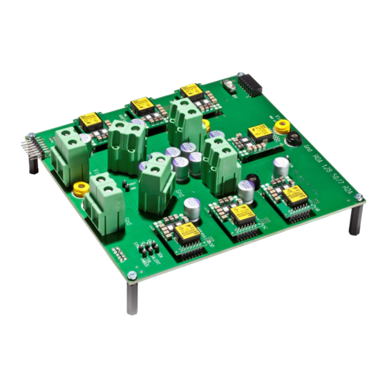
- Page 1 Evaluation Board User Guide ROA 128 5077 User Guide for paralleling BMR463, BMR463...
-
Page 2: Table Of Contents
Contents Introduction ..................3 How to contact Flex Power Modules ..........3 User Guide ..................3 Power up/down instructions ..............3 Power supply connections ..............3 Address and v out range resistors ...........6 Change of address resistors ..............7 BMR463/464 adjustment of address resistors ........7 Dimensions ..................8... -
Page 3: Introduction
Introduction This User Guide provides a brief introduction and instruction on how to use the Reference Board ROA 128 5077 for paralleling of BMR463 and BMR464. How to contact Flex Power Modules For general questions or interest in our products, please contact your local sales representative. - Page 4 Figure 2 shows the RC switch in “On” position. SW 1 Figure 2: RC switch in ‘On’ position Figures 3 & 4 show the connection of two types of USB-to-PMBus adapters. Figure 3: Connection o FPM KEP91017 PMBus to USB adapter Evaluation Board User Guide –...
- Page 5 Figure 4: Connection of the Intersil ZLUSBREF02 PMBus to USB adapter Power-up instructions: Mount the BMRs in desired positions • Turn the RC switch in ‘Off’ position • Connect and turn on 5-14 V supply • Connect the PMBus adapter/cable to the board •...
-
Page 6: Address And V Out Range Resistors
Address and v out range resistors This section describes the locations of the Address and Vout range pin strap resistors. To know what resistor value to mount, please look in the actual Technical Specification of the BMR product found on our website. -
Page 7: Change Of Address Resistors
BMR463/464 adjustment of address resistors To change the address in a position, change the resistors as shown in figure 6. See table below for each position of resistors. Figure 6: Address resistors in position for BMR463/464 PoL position Address Vout range... -
Page 8: Dimensions
Dimensions The outer dimensions (in mm) of the test board are shown in the picture below. The whole test board has the outer dimensions 150 x 160 x 56.5 mm (L x W x H). Weight of the complete test board is 370 g. Evaluation Board User Guide –... -
Page 9: Revision
The contents of this document are subject to revision without notice due to continued progress in methodology, design and manufacturing. Flex shall have no liability for any error or damage of any kind resulting from the use of this document.
Need help?
Do you have a question about the BMR463 and is the answer not in the manual?
Questions and answers