Table of Contents
Advertisement
Operators Manual
MODELS:
KGT-6-T
KGT-12-T
™
Cleveland
Enodis
Installation, Operation & Service
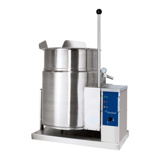
Gas Table Top Kettles
For models built after July 2002
1333 East 179th St., Cleveland, Ohio, U.S.A. 44110
Phone: (216) 481-4900 Fax: (216) 481-3782
Visit our web site at www.clevelandrange.com
SE95010 Rev. 9
Advertisement
Table of Contents

Related Manuals for Cleveland KGT-12-T


Summary of Contents for Cleveland KGT-12-T
- Page 1 Operators Manual MODELS: KGT-6-T KGT-12-T ™ Cleveland Enodis Installation, Operation & Service Gas Table Top Kettles For models built after July 2002 1333 East 179th St., Cleveland, Ohio, U.S.A. 44110 Phone: (216) 481-4900 Fax: (216) 481-3782 Visit our web site at www.clevelandrange.com...
-
Page 2: For The User
YOUR LOCAL GAS SUPPLIER. KEEP APPLIANCE AREA FREE AND CLEAR FROM COMBUSTIBLES. DO NOT OBSTRUCT THE FLOW OF COMBUSTION AND VENTILATION AIR. ALL SERVICE MUST BE PERFORMED BY A QUALIFIED CLEVELAND RANGE TECHNICIAN. RETAIN THIS MANUAL FOR YOUR REFERENCE. FOR THE USER... -
Page 3: Installation
CLEARANCE REQUIREMENTS TO COMBUSTIBLE AND NONCOMBUSTIBLE SURFACES. Model # Back Left Side KGT-6-T 4” KGT-12-T 4” NOTE: To prevent removal of unit for servicing, allow sufficient room on right hand side for servicing. ASSEMBLY 2 3/8" - 6 gallon 14 1/2"... -
Page 4: Installation Checks
Installation must be in accordance with local codes and/or the National Fuel Gas Code ANSI Z223.1 Latest Edition (USA) or the latest Installation Codes for Gas Burning Appliances and Equipment CAN/ CGA B149.1 and CAN/ CGA B149.2 (Canada). Use a gas pipe joint compound which is resistant to L.P. -
Page 5: Operating Instructions
OPERATING INSTRUCTIONS General Parts Drawing ITEM # DESCRIPTION Tilting Handle Vacuum/Pressure Gauge Pressure Relief Valve Heat Indicator Light (Green) Low Water Indicator Light (Red) Ignition Failure Indicator Light (Amber) On-Off Switch/ Solid State Temperature Control Marine Lock Water Level Sight Glass FUNCTION Used for tilting the kettle. -
Page 6: Operating The Kettle
OPERATING THE KETTLE DO NOT ATTEMPT TO OPERATE THIS APPLIANCE DURING A POWER FAILURE. KEEP APPLIANCE AND AREA FREE AND CLEAR OF COMBUSTIBLES. DO NOT LEAN ON OR PLACE OBJECTS ON KETTLE LIP. SERIOUS INJURY COULD RESULT IF KETTLE TIPPED OVER, SPILLING HOT CONTENTS. Before turning kettle on, read the Vacuum/Pressure Gauge (2). -
Page 7: Marine Lock
MARINE LOCK Your unit is equipped with a marine lock to prevent accidental tilting. The following procedure should be used to tilt the kettle. 1. Grasp the tilt handle. CLEANING INSTRUCTIONS CAUTION SURFACES MAY BE EXTREMELY HOT! CARE AND CLEANING Cooking equipment must be cleaned regularly to maintain its fast, efficient cooking performance and to ensure its continued safe, reliable operation. -
Page 8: Stainless Steel Equipment Care And Cleaning
STAINLESS STEEL EQUIPMENT CARE AND CLEANING (Suppied courtesy of Nafem. For more information visit their web site at www.nafem.org) Contrary to popular belief, stainless steels ARE susceptible to rusting. Corrosion on metals is everywhere. It is recognized quickly on iron and steel as unsightly yellow/orange rust. -
Page 9: Service Parts
SERVICE PARTS WARRANTY Our Company supports a worldwide network of Maintenance and Repair Centers. Contact your nearest Maintenance and Repair Centre for replacement parts, service, or information regarding the proper maintenance and repair of your cooking equipment In order to preserve the various agency safety certification (UL, NSF, ASME/Ntl. Bd., etc.), only factory-supplied replacement parts should be used. -
Page 10: Console Components
CONSOLE COMPONENTS (used after June 2005) ITEM # PART # KE600545 KE50753-7 KE00458 KE50303-2 KE50303-1 FA11145 FA15018-7 FA11091 KE53838-20 KE53838-18 KE53838-27 KE53838-21 KE53469-2 KE600567 FA21006 FA15018-8 KE54309 KE54308-1 KE600566 FA11256 WHKGT-2 FA95074 FA31010 FA21026 20 21 DESCRIPTION COMPONENT MOUNTING BRACKET ....... . 1 RELAY . - Page 11 CONSOLE COMPONENTS (used prior to June 2005) 14 15 ITEM # PART # KE01928-3 KE01927-2 KE50753-7 KE00458 KE50303-2 FA11089 FA11052 KE53838-27 KE53838-21 KE53838-20 KE53838-18 KE53469-2 FA10245 KE54308-3 KE54309 WHKGT KE600252 KE90424 FA95062 DESCRIPTION COMPONENT PLATE ASSEMBLY ........1 COMPONENT MOUNTING PLATE WELDMENT .
-
Page 12: Trunnion Assembly
TRUNNION ASSEMBLY (used after June 2005) ITEM # PART # FA21024 FA31030 KE600343 FA11323 KE01917-1 FA95007-11 FA05002-49 FA05002-45 KE54434-1 TRUNNION ASSEMBLY (used prior to June 2005) ITEM # PART # FA05002-45 KE54434-1 FA95007-11 DESCRIPTION HEX NUT, SS, 5/16-18 ..........4 HELICAL SPRING LOCK WASHER, SS, 5/16"... -
Page 13: Switches And Indicators
SWITCHES & INDICATORS (used after June 2005) ITEM # PART # KE55486-3 KE55486-2 KE55486-4 KE600537 FA21006 KE600560-B SE00114 KE51005 KE50569-1 O F F DESCRIPTION INDICATOR LIGHT, GREEN ........1 INDICATOR LIGHT, RED . - Page 14 SWITCHES & INDICATORS (used prior to June 2005) ITEM # PART # SE00114 KE51005 KE50569-1 KE50567-1 FA05002-18 KE50567-3 KE50567-2 KE5555-5 DESCRIPTION POTENTIOMETER WITH ON/OFF SWITCH, C/W ITEM #2 ....1 ROTARY SEAL .
- Page 15 MAIN COMPONENTS ITEM # PART # SK50403 SK50434 FA95081-3 KE54247 KE02004-2 KE50474 KE50429-5 KE54941-5 KE54941-31 KE50151-1 KE54670-4 KE54670-5 FA30501-1 KE54435-4 FA11258 KE54821-8 KE54721-2 KE54468 KE55069-6 KE50294-1 KE00515 KE54246-3 DESCRIPTION BRONZE BEARING ..........1 WASHER .
-
Page 16: Piping Assembly
PIPING ASSEMBLY TO MAIN GAS SUPPLY... - Page 17 BURNER ONLY (KGT-12-T) ........
-
Page 18: Inspection And Maintenance Check List
ALL SERVICE MUST BE PERFORMED BY A QUALIFIED SERVICE TECHNICIAN. Cleveland Range equipment requires little preventative maintenance. We do however provide the following chart as a guideline for inspection and maintenance to keep your unit functioning at 100%. INSPECTION AND MAINTENANCE CHECK LIST The following check should be completed every six months or more frequently if unit is in a high volume facility. -
Page 19: Calibrating Procedure
CALIBRATING PROCEDURE Insure the unit has a vacuum before you begin calibrating procedures. If unit requires venting refer to Kettle Venting Instructions. Set On-Off Switch/Temperature Control to "10" (Max.). Allow the unit to cycle twice. Check temperature of the inner kettle surface with a digital surface thermometer. -
Page 20: Reservoir Fill Procedures
RESERVOIR FILL PROCEDURES WARNING: IMPROPER REFILLING OF KETTLE JACKET WILL RESULT IN IRREVERSIBLE DAMAGE TO UNIT. The kettle's water level must be maintained at the proper level. Under normal operating conditions, the sealed water reservoir should never require the addition of water. - Page 21 KETTLE JACKET CLEANOUT AND PASSIVATION PROCEDURES The following procedure should be preformed at least once every three years to prevent possible corrosion and ensure the optimum life of the kettle. WARNING: IMPROPER REFILLING OF KETTLE JACKET WILL RESULT IN IRREVERSIBLE DAMAGE TO UNIT DANGER: MOLYFILM 315 IS CORROSIVE, AVOID CONTACT WITH SKIN AND EYES.
-
Page 22: Kettle Venting Instructions
KETTLE VENTING INSTRUCTIONS Pressure Gauge Pressure Relief Valve The following venting procedure should be followed when the Vacuum/Pressure Gauge needle is in the "VENT AIR" zone: NOTE: Check for and eliminate leaks prior to venting (See Repairing Leaks in Steam Jacketed Kettle Fittings. DANGER: PRESSURE RELIEF VALVE WILL EXHAUST HIGH... -
Page 23: Wiring Diagram
WIRING DIAGRAM ITEM # PART # KE55486-2 KE50567-1 KE55486-3 KE50567-3 KE55486-2 KE50567-2 SE00114 KE00458 KE00515 KE50556-1 KE50753-7 KE50294-1 KE53838-27 KE53838-21 KE53437-1 KE55069-6 KE53469-2 KE53838-20 KE53838-18 KE55240-8 KE55240-7 DESCRIPTION L.E.D., RED (USED AFTER JUNE 2005) L.E.D., RED (USED PRIOR TO JUNE 2005) L.E.D., GREEN (USED AFTER JUNE 2005) L.E.D., GREEN (USED PRIOR TO JUNE 2005) L.E.D., AMBER (USED AFTER JUNE 2005) -
Page 24: Operating Sequences
OPERATING SEQUENCES Turn On-Off Switch/ Temperature Control Knob "ON" Ignitor Sparks Temperature Reached Maintaining Temperature SOLID STATE CONTROL SEQUENCE Our solid state controls consist of the following components. On-Off Switch/ Provides or interrupts electrical power to the control system. Temperature Rotate to change resistance from 0 to 50,000 ohms. -
Page 25: Marine Lock Testing Procedure
MARINE LOCK TESTING PROCEDURE 1. Check that lock clears stop pin on side box without rubbing when kettle is tilted (Figure A). 2. Check side to side play. Lock should remain fully over stop pin when pushed to it's maximum side to side play (Figure B).
Need help?
Do you have a question about the KGT-12-T and is the answer not in the manual?
Questions and answers