Cleveland KGL-25 Operator's Manual
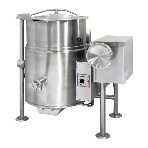
Gas 25 gallon kettle
Hide thumbs
Also See for KGL-25:
- Operator's manual (36 pages) ,
- Specifications (2 pages) ,
- Installation operation & maintenance (34 pages)
Table of Contents
Advertisement
Advertisement
Table of Contents

Related Manuals for Cleveland KGL-25


Summary of Contents for Cleveland KGL-25
- Page 1 Operators Manual MODELS: KGL-25 KGL-25-T KGT-25 KGT-25-T ™ Cleveland Enodis Installation, Operation & Service Gas 25 Gallon Kettle 1333 East 179th St., Cleveland, Ohio, U.S.A. 44110 Phone: (216) 481-4900 Fax: (216) 481-3782 Visit our web site at www.clevelandrange.com SE95052 Rev. 3...
-
Page 2: For The User
YOUR LOCAL GAS SUPPLIER. KEEP APPLIANCE AREA FREE AND CLEAR FROM COMBUSTIBLES. DO NOT OBSTRUCT THE FLOW OF COMBUSTION AND VENTILATION AIR. ALL SERVICE MUST BE PERFORMED BY A QUALIFIED CLEVELAND RANGE TECHNICIAN. RETAIN THIS MANUAL FOR YOUR REFERENCE. FOR THE USER... -
Page 3: Gas Appliances
For your safety Keep clear of pressure relief discharge. Inspect unit daily for proper operation. Surfaces may be extremely hot! Use protective equipment. Do not lean on or place objects on kettle lip. Shut off power at main fuse disconnect prior to servicing. -
Page 4: Installation
INSTALLATION INSPECTION Before unpacking visually inspect the unit for evidence of damage during shipping. If damage is noticed, do not unpack the unit, follow shipping damage instructions. SHIPPING DAMAGE INSTRUCTIONS If shipping damage to the unit is discovered or suspected, observe the following guidelines in preparing a shipping damage claim. -
Page 5: Installation Checks
Code, ANSI/NFPA 70-1990 (USA) or the Canadian Electrical Code, CSA C22.2, Part 1 (Canada). VENTILATION Gas fired kettles are only to be installed under a ventilation hood in a room which has provisions for adequate make up air. Further information can be obtained by referring to the U.S.A. -
Page 6: Operating Instructions
Cycles ON-OFF with burner. Displays water level in steam jacket. Indicates failure of heating system to ignite. Used for draining product or wash water from kettle. It is supplied as standard equipment on stationary kettles and is optional on tilting kettles. -
Page 7: Operating The Kettle
° C APPROXIMATE BOILING TIMES The accompanying chart shows approximate times required for electric kettles of various capacities to boil water. The ON/OFF Switch/Solid State Temperature Control (5) must be set at “10” (Max.) throughout the heat-up period. Water will boil about 1/3 faster if the kettle is filled only to the outer steam jacket’s welded... -
Page 8: Cleaning Instructions
CLEANING INSTRUCTIONS CAUTION SURFACES MAY BE EXTREMELY HOT! CARE AND CLEANING Cooking equipment must be cleaned regularly to maintain its fast, efficient cooking performance and to ensure its continued safe, reliable operation. The best time to clean is shortly after each use (allow unit to cool to a safe temperature). -
Page 9: Stainless Steel Equipment Care And Cleaning
STAINLESS STEEL EQUIPMENT CARE AND CLEANING (Suppied courtesy of Nafem. For more information visit their web site at www.nafem.org) Contrary to popular belief, stainless steels ARE susceptible to rusting. Corrosion on metals is everywhere. It is recognized quickly on iron and steel as unsightly yellow/orange rust. -
Page 10: Service Parts
FOR STATIONARY KETTLES ...1 KE50825-2 FOR TILTING KETTLES ....1 FA95022 RETAINING RING ....1 FA05002-19 "O"... -
Page 11: Stationary Models
COMPONENT MOUNTING PLATES STATIONARY MODELS ITEM NO. PART NO. KE01927-1 KE01927 KE50753-7 KE00458 KE50303 KE52548 FA11089 FA11052 FA32004 FA32005 11.* KE53469-2 KE54308-3 12.* FA10245 13.* FA20004 KE53838-20 KE53838-27 KE53838-18 KE53838-21 * FOR TILTING MODELS SEE “GENERAL ASSEMBLY - TILTING MODELS” DESCRIPTION COMPONENT MOUNTING PLATE (STATIONARY MODELS) . -
Page 12: Burner Assembly
BURNER ASSEMBLY ITEM NO. PART NO. KE54897-1 KE54890-1 FA11144 KE54881-1 KE54894-1 KE54895-3 KE01500-2 KE01500-4 KE02195-1 KE54895-2 KE54895-4 KE53406-21 KE53406-18 FI05134-1 FI00565-6 KE53437-1 FA11145 KE54775 4 5 6 DESCRIPTION MANIFOLD ........... . .1 IGNITION GUARD . -
Page 13: Tangent Draw-Off Valve
TANGENT DRAW-OFF VALVE ITEM NO. PART NO. 1. - 7. KE50973 KE50972-B FA95049 FA21050 FA21501-1 KE52755 SE50018 FI05180-1 FI05180-2 KE52753 SE50013 KE52752 SE50010 FA05002-24 FA05002-38 KE50972-B KE50973 DESCRIPTION 2” DRAW-OFF ASSEMBLY .........1 3”... -
Page 14: General Assembly
GENERAL ASSEMBLY - STATIONARY MODELS (pg. 1 of 2) 7 8 10 10 L1 14 15 16 VIEW "A" COMPONENT MOUNTING BOX WITH LID REMOVED 19 20 VIEW "B" MANIFOLD & BURNER TUBE PIPING DETAIL... - Page 15 GENERAL ASSEMBLY - ITEM NO. PART NO. KE00099 KE01928-2 FA20006 FA32006 KE54991-1 KE54991-2 FA95074 KE54846-4 KE54846-5 FA95031 KE000714-4 KE50429-5 KE54941-6 KE55069-6 KE00515 KE50556-1 KE02053 FA10360 F01518-1 KE54618-1 KE54618-2 FI00607 KE54821-8 KE54833-2 FA00152 FI00355 FI00565-3 FI05198-5 FI00265 FI05134-1 KE54667-4 FI00565-6 KE51238 CHS-25 KE54468 LABELS...
- Page 16 PART NO. KE00099 KE51723-1 KE000714-4 KE50429-5 KE529773 KE00508 KE54821-8 CHS-KGL-25-T KE00351 FI05321-1 KE54667-3 TILTING MODELS (pg. 1 of 3) MANIFOLD & BURNER TUBE PIPING DETAIL 60 L5 DESCRIPTION ADJUSTABLE FOOT ..........1 SAFETY VALVE (50 PSI) .
- Page 17 GENERAL ASSEMBLY - 39 40 41 36 42 43 45 43 42 Gear box same as KGL-40 to 100-T FI05134-1 FI05198-5 FI00565-6 FI05222 FI05231 FI05223 KE02053 FI00607 F01518-1 GAS OPTIONS : KE54618-1 KE54618-2 F105226-12 TILTING MODELS (pg. 2 of 3) KE517112 LH BEARING KE51712 GREASE NIPPLE KE51711 RH BEARING...
- Page 18 GENERAL ASSEMBLY - FI00040 FA19177 FA20047 KE50294-1 KE54456-1 KE50295-1 FA11396 FA31031 FA15018-7 KE52833 FA10772 FA20030 FA95007-4 FA95055-1 KE50315 KE51730 FA31010 FA20030 KE503752 FA95005 KE52193 KE52191 KE52192 FA30088 FA95008 KE53469-2 KE54308-4 FA10245 FA20004 FA32005 KE53390 FA10367 FA32006 FA20007 KE55069-6 KE00515 KE50556-1 KE01928-1 FA20006 FA11145...
-
Page 19: Console Controls
CONSOLE CONTROLS ITEM NO. PART NO. SE00114 KE51005 KE50569-1 SE003013-1 SE003013-2 SE003013-3 FA05002-18 DESCRIPTION POTENTIOMETER WITH ON/OFF SWITCH, C/W ITEM #2 ....1 RUBBER BOOT ..........1 KNOB, POTENTIOMETER . -
Page 20: Hinge Assembly
HINGE ASSEMBLY ITEM NO. PART NO. 1. - 11 KE50597-1 KE50597-2 KE50597-3 KE50597-4 KE50597-5 KE50822 KE51217 KE50121-2 KE50121-1 KE50823-1 KE50824 KE50819-1 KE50820 KE50819 FA11284 FA11507 SK50418 KE50151-2 DESCRIPTION Hinge Assembly 25 - 40 Gallon, 20 Gallon Full Jacketed .......1 60 - 80 Gallon, 30 - 40 Gallon Full Jacketed . -
Page 21: Inspection And Maintenance Checklist
PRESSURE GAUGE IS SHOWING ZERO OR LESS PRESSURE PRIOR TO REMOVING ANY FITTINGS. Cleveland Range equipment requires little preventative maintenance. We do however provide the following chart as a guideline for inspection and maintenance to keep your unit functioning at 100%. -
Page 22: Safety Inspection Checklist
No safety features designed into the equipment should ever be tampered with. Tampering with or bypassing controls is a very dangerous practice and unfortunately we have seen several cases of this. Following is a short list of the most common and the most dangerous alterations performed on kettles. SAFETY VALVE: ✔... -
Page 23: Safety Thermostat
SAFETY INSPECTION CHECKLIST TILTING MODELS (pg. 2 of 2) SAFETY THERMOSTAT: ✔ Probe fully inserted in tube Wiring is properly connected Low Water Level Probe: ✔ Probe properly attached Operating Thermostat: ✘ ✘ Probe Probe removed removed partially completely ✘ Probe bypassed by running (A) an additional wire... -
Page 24: Lubrication Procedure
LUBRICATION PROCEDURE Lubricate the following parts every three months to insure smooth operation and reduce wear. TRUNNION Adjusting HOUSING, Screw WORM SCREW AND TILT GEAR Worm Screw and These parts are Tilt accessed through the Gear top cover of the Cross console. -
Page 25: Calibrating Procedure
CALIBRATING PROCEDURE Insure the unit has a vacuum before you begin calibrating procedures. If unit requires venting refer to Kettle Venting Instructions. Set On-Off Switch/Temperature Control to "10" (Max.). Allow the unit to cycle twice. Check temperature of the inner kettle surface with a digital surface thermometer. -
Page 26: Reservoir Fill Procedures
Ensure that the red "low water" light is on when the kettle is upright. On tilting kettles, it is normal for the red light to come on when the kettle is in a tilted position. - Page 27 KETTLE JACKET CLEANOUT AND PASSIVATION PROCEDURES The following procedure should be preformed at least once every three years to prevent possible corrosion and ensure the optimum life of the kettle. WARNING: IMPROPER REFILLING OF KETTLE JACKET WILL RESULT IN IRREVERSIBLE DAMAGE TO UNIT DANGER: MOLYFILM 315 IS CORROSIVE, AVOID CONTACT WITH SKIN AND EYES.
-
Page 28: Kettle Venting Instructions
KETTLE VENTING INSTRUCTIONS Pressure Gauge Pressure Relief Valve The following venting procedure should be followed when the Vacuum/Pressure Gauge needle is in the "VENT AIR" zone: NOTE: Check for and eliminate leaks prior to venting (See Repairing Leaks in Steam Jacketed Kettle Fittings. DANGER: PRESSURE RELIEF VALVE WILL EXHAUST HIGH... - Page 29 Natural Gas to Propane Gas Atmospheric Burner Gas Kettles BTU's per Water Hour Type Column Orifices KGT-6-T 34000 34000 KGT-12-T 53000 53000 KGL-25, KGL-25-T 90000 90000 IS C IDENTIFICATION T E D STICKER COMBINATION VALVE GASKET PRESSURE REGULATOR UNIT NOTE: Use thread sealant compatible with propane gas on all threaded piping connections.
-
Page 30: Wiring Diagram
WIRING DIAGRAM TABLE-TOP GAS KETTLE, 120-240 VOLTS KE90424-F... -
Page 31: Sequence Of Operations
SEQUENCE OF OPERATIONS To turn the unit on, turn the switch to the on position. ■ Power is sent to primary side of the 120vac/16vac transformer. ■ Power is sent to the normally closed high limit. ■ From the high limit power is sent to the normally open contacts of the 12VDC relay. - Page 32 PROBLEM: KGL-25 Kettle Won't Heat Replace Is 16 VAC at the the on/off secondary side of switch (toggle the transformer? or rotary). Is there 115 VAC Replace the to the primary of transformer. the transformer? Supply115 VAC to the kettle.
-
Page 33: Kettle Not Hot Enough
PROBLEM: KGL-25 Kettle Not Hot Enough Vent the kettle per instructions in the manual. Replace controller. Does the kettle heat at all? kettle won't heat. With kettle pot empty and temperature knob set at 10, is the temperature of the... - Page 34 PROBLEM: KGL-25 Kettle Gets kettle is working properly. Too Hot Replace the gas valve. Replace the Relay PROBLEM: Red Add Water LED Stays On Add the proper amount of distilled water and rust inhibitor. Clean or replace water probe. Replace the wire harness in the trunion.
Need help?
Do you have a question about the KGL-25 and is the answer not in the manual?
Questions and answers