Table of Contents
Advertisement
Quick Links
Getting started with the AEK-POW-LDOV01J and AEK-POW-LDOV01S
Introduction
The
AEK-POW-LDOV01J
and
voltage regulator ICs, which are two different versions of the L99VR01.
The
L99VR01
is a DC-DC voltage regulator designed for automotive applications (AEC-Q100 qualified). It can deliver up to 200
mA of load current and consumes around 1 μA when the regulator is disabled.
The operating input voltage is between 2.15 and 28 V, while a fixed selectable output voltage (0.8 V, 1.2 V, 1.5 V, 1.8 V, 2.5 V,
2.8 V, 3.3 V, or 5 V) is configurable.
UM3028 - Rev 1 - July 2022
For further information contact your local STMicroelectronics sales office.
automotive-grade LDOs with configurable output voltage
AEK-POW-LDOV01S
evaluation boards host, respectively, the
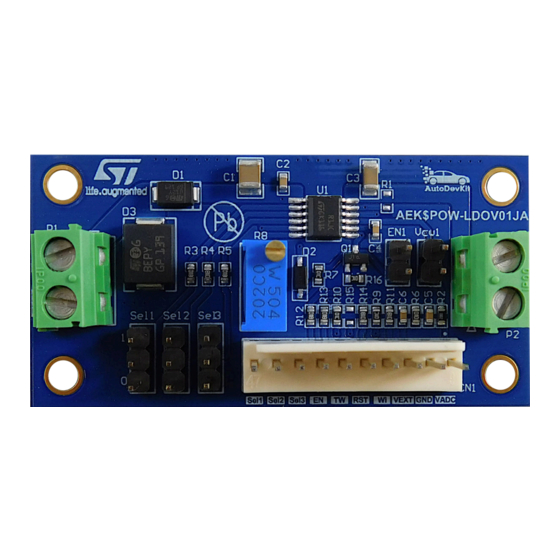
Figure 1.
AEK-POW-LDOV01J evaluation board
Figure 2.
AEK-POW-LDOV01S evaluation board
UM3028
User manual
L99VR01JTR
and
L99VR01STR
www.st.com
Advertisement
Table of Contents

Related Manuals for ST AEK-POW-LDOV01J


Summary of Contents for ST AEK-POW-LDOV01J
-
Page 1: Figure 1. Aek-Pow-Ldov01J Evaluation Board
UM3028 User manual Getting started with the AEK-POW-LDOV01J and AEK-POW-LDOV01S automotive-grade LDOs with configurable output voltage Introduction AEK-POW-LDOV01J AEK-POW-LDOV01S evaluation boards host, respectively, the L99VR01JTR L99VR01STR voltage regulator ICs, which are two different versions of the L99VR01. Figure 1. AEK-POW-LDOV01J evaluation board Figure 2. -
Page 2: Figure 3. L99Vr01Jtr Functional Block
L99VR01JTR functional block Figure 4. L99VR01STR functional block AEK-POW-LDOV01J AEK-POW-LDOV01S boards can be used in a standalone configuration or with an external microcontroller. In the latter case, the MCU provides a watchdog signal to the regulator to monitor the active connection. -
Page 3: Getting Started
Overcurrent monitoring and lost ground protection The overcurrent limit is set by regulating a current on the Ishort through an external potentiometer available on the AEK-POW-LDOV01J. If the overcurrent limit is reached, the RST pin is pulled low. • Thermal warning detection To warn the microcontroller about a severe temperature increase of the LDO, a thermal warning output has been implemented. -
Page 4: Hardware Architecture
UM3028 Hardware architecture Hardware architecture AEK-POW-LDOV01J AEK-POW-LDOV01S evaluation boards are equipped with: • CN1 connector: used only if the board is connected to an external microcontroller. Table 1. CN1 pin description Description Sel1 Sel2, Sel3 Output voltage selectors Enable input... -
Page 5: Enable Pin
Then, the current consumption of the device is about 1 μA. Figure 5. Enable and disable signals The EN input pin or the EN1 jumper enable/disable the AEK-POW-LDOV01J/AEK-POW-LDOV01S, as follows: • when the EN pin is set to high, it is forced to low and the output is switched off;... -
Page 6: Output Voltage Selection
The watchdog is an automotive safety mechanism used to monitor a continuous connection with an external MCU. The watchdog signal (generated by the MCU and applied to the AEK-POW-LDOV01J WI pin) is a square wave with a duty cycle equal to 50%. Its frequency value depends on both the output voltage and the chosen C4... -
Page 7: Overvoltage Warning (For The Aek-Pow-Ldo01J Only)
UM3028 Overvoltage warning (for the AEK-POW-LDO01J only) Overvoltage warning (for the AEK-POW-LDO01J only) The TW pin provides the output overvoltage (OV) diagnostic. To distinguish between a thermal warning and an output overvoltage event, two different signals are generated on the same TW output pin. A thermal warning event detection sets the TW pin low. -
Page 8: Software Architecture
Software architecture Software architecture According to the AutoDevKit paradigm, several MCU boards can be connected to the AEK-POW-LDOV01J/AEK- POW-LDOV01S evaluation board. The smallest available MCU is the SPC582B Chorus 1M. AutoDevKit ecosystem fully supports the hardware. This ecosystem consists of: •... -
Page 9: Init Device
RESET: this state detects a falling reset signal. It returns to the normal state when the V output voltage rises above V and the watchdog frequency value is correct (for the AEK-POW-LDOV01J only) • ERROR: the FSM enters this state when the absolute value of the difference between the V... -
Page 10: Power Off
UM3028 AEK-POW-LDOV01x software library architecture Note: Before proceeding with the power on, set the output voltage by using the SELx pins. 3.3.3 Power off To turn the AEK-POW-LDOV01x off, an enable off transaction is required. The AEK-POW-LDOV01x software library includes the following power off instruction: void AEK_POW_LDOV01x_power_off (uint8_t AEK_POW_LDOV01x_n_device);, where the AEK_POW_LDOV01x_n_device represents the allocated AEK-POW-LDOV01x board. -
Page 11: Demo In The Autodevkit
Demo in the AutoDevKit Demo in the AutoDevKit How to create a sample application for the AEK-POW-LDOV01x This example explains how to create an application for the AEK-POW-LDOV01J/AEK-POW-LDOV01S. The microcontroller board used is the AEK-MCU-C1MLIT1. Step 1. Create a new... -
Page 12: Available Demos For The Aek-Pow-Ldov01X
UM3028 Available demos for the AEK-POW-LDOV01x Step 4. Click on [+] to add a new element to the board list. Figure 10. Adding a new element Step 5. Double-click on the newly added element to configure the board. Step 6. Select the voltage regulator part number. -
Page 13: How To Upload The Demos
UM3028 Available demos for the AEK-POW-LDOV01x AEK-POW-LDOV01J board demo goal is to generate a fixed output voltage (5 V). If an overvoltage warning or thermal warning event occurs, the regulator is switched off. Figure 12. Demo code Note: If the... -
Page 14: Figure 13. Mcu Family Selection
UM3028 Available demos for the AEK-POW-LDOV01x Step 2. Insert the appropriate MCU family details. Figure 13. MCU family selection Step 3. Select the desired application from the library. Figure 14. Application selection Step 4. Click the [Finish] button. UM3028 - Rev 1 page 14/37... -
Page 15: Apis
UM3028 APIs APIs void AEK_POW_LDOV01x_init(uint8_t AEK_POW_LDOV01x_n_device); This function initializes the AEL_POW_LDOV01x. void AEK_POW_LDOV01x_initAll(); This function initializes all the AEL_POW_LDOV01x. void AEK_POW_LDOV01x_power_on(uint8_t AEK_POW_LDOV01x_n_device); This function turns on the AEK_POW_LDOV01x. void AEK_POW_LDOV01x_power_off(uint8_t AEK_POW_LDOV01x_n_device); This function turns off the AEK_POW_LDOV01x. void AEK_POW_LDOV01x_setOperationMode(AEK_POW_LDOV01x_op_mode_t op_mode, uint8_t AEK_POW_LDOV01x_n_device);... -
Page 16: Test Results
UM3028 Test results Test results Figure 15. Enable pulse signal waveform generated by an external MCU connected to the AEK-POW- LDOV01J UM3028 - Rev 1 page 16/37... -
Page 17: Figure 16. Watchdog Signal Waveform Generated By An External Mcu Connected To The Aek-Pow-Ldov01J
UM3028 Test results Figure 16. Watchdog signal waveform generated by an external MCU connected to the AEK-POW- LDOV01J (operating voltage selected = 5 V) UM3028 - Rev 1 page 17/37... -
Page 18: Figure 17. Output Voltage Waveform Generated By The Aek-Pow-Ldov01J After Power On
UM3028 Test results Figure 17. Output voltage waveform generated by the AEK-POW-LDOV01J after power on (operating voltage selected = 5 V) UM3028 - Rev 1 page 18/37... -
Page 19: Figure 18. Thermal Warning Waveform Generated By The Aek-Pow-Ldov01J After Power On
UM3028 Test results Figure 18. Thermal warning waveform generated by the AEK-POW-LDOV01J after power on (operating voltage selected = 5 V) UM3028 - Rev 1 page 19/37... -
Page 20: Figure 19. Overvoltage Warning Waveform Generated By The Aek-Pow-Ldov01J (Operating Voltage Selected = 5 V)
UM3028 Test results Figure 19. Overvoltage warning waveform generated by the AEK-POW-LDOV01J (operating voltage selected = 5 V) UM3028 - Rev 1 page 20/37... -
Page 21: Figure 20. Reset Signal Waveform Generated By The Aek-Pow-Ldov01J If The V O Output Voltage Is Lower Than The V Th
UM3028 Test results Figure 20. Reset signal waveform generated by the AEK-POW-LDOV01J if the V output voltage is lower than the V threshold UM3028 - Rev 1 page 21/37... -
Page 22: Aek-Pow-Ldov01J Schematic Diagrams
AEK-POW-LDOV01J schematic diagrams Figure 21. AEK-POW-LDOV01J circuit schematic STTH102AY 10uF 100nF SMCJ24CA-TR STPS0540ZY 3.3uF Vcw1 N.M. L99VR01JTR Sel1 Vo_ADC R31K Sel2 1KR4 Sel3 1KR5 hort 100K 47nF VEXT 500K BSS138Q Sel1 SEL1 Sel2 SEL2 Sel3 SEL3 1KR12 1KR11 Sel1 Sel2 Sel3... -
Page 23: Aek-Pow-Ldov01S Schematic Diagrams
AEK-POW-LDOV01S schematic diagrams Figure 22. AEK-POW-LDOV01S circuit schematic STTH102AY 3.3uF 10uF 100nF SMCJ24CA-TR STPS0540ZY Vo_ADC N.M. L99VR01STR 100K Sel1 1KR4 Sel1 Sel2 1KR5 Sel2 VEXT Sel3 R61K Sel3 Sel1 SEL1 Sel2 SEL2 Sel3 SEL3 Sel3 Sel1 Sel2 Vo 1KR10 1KR9 VEXT VEXT BSS138Q... -
Page 24: Aek-Pow-Ldov01J Bill Of Materials
UM3028 AEK-POW-LDOV01J bill of materials AEK-POW-LDOV01J bill of materials Table 6. AEK-POW-LDOV01J bill of materials Item Q.ty Ref. Part/value Description Manufacturer Order code 10uF, 1210C, 1210 capacitor - Wurth 885012209073 50V, ±10% X7R Class II Elektronik 100nF, 0603C, 0603 capacitor -... - Page 25 UM3028 AEK-POW-LDOV01J bill of materials Item Q.ty Ref. Part/value Description Manufacturer Order code Automotive linear voltage regulator with L99VR01JTR, configurable L99VR01JTR PowerSSO-12 output voltage and 200 mA current capability Jumper 2.54 Wurth 60900213421 60900213421 Elektronik Nylon spacer Wurth 970100365 970100365...
-
Page 26: Aek-Pow-Ldov01S Bill Of Materials
UM3028 AEK-POW-LDOV01S bill of materials AEK-POW-LDOV01S bill of materials Table 7. AEK-POW-LDOV01S bill of materials Item Q.ty Ref. Value Description Manufacturer Order code 10µF, 1210C, 1210 capacitor - 885012209073 50 V, ±10 % X7R class II 100nF, 0603C, 0603 capacitor - C2, C4, C5 885012206095 50 V, ±10 %... - Page 27 UM3028 AEK-POW-LDOV01S bill of materials Item Q.ty Ref. Value Description Manufacturer Order code Automotive linear voltage regulator with L99VR01STR, configurable L99VR01STR SO-8 output voltage and 200 mA current capability Jumper 2.54 Wurth 60900213421 60900213421 Elektronik Nylon spacer Wurth 970100365 970100365 M3x10 mmF/F Elektronik Nylon screw...
-
Page 28: Aek-Pow-Ldov01J Versions
AEK-POW-LDOV01J versions PCB version Schematic diagrams Bill of materials AEK$POW-LDOV01JA AEK$POW-LDOV01JA schematic diagrams AEK$POW-LDOV01JA bill of materials 1. This code identifies the AEK-POW-LDOV01J evaluation board first version. It is printed on the board PCB. UM3028 - Rev 1 page 28/37... -
Page 29: Aek-Pow-Ldov01S Versions
UM3028 AEK-POW-LDOV01S versions AEK-POW-LDOV01S versions Table 9. AEK-POW-LDOV01S versions PCB version Schematic diagrams Bill of materials AEK$POW-LDOV01SA AEK$POW-LDOV01SA schematic diagrams AEK$POW-LDOV01SA bill of materials 1. This code identifies the AEK-POW-LDOV01S evaluation board first version. It is printed on the board PCB. UM3028 - Rev 1 page 29/37... -
Page 30: Aek-Pow-Ldov01J Regulatory Compliance Information
UM3028 AEK-POW-LDOV01J regulatory compliance information AEK-POW-LDOV01J regulatory compliance information Formal Notice Required by the U.S. Federal Communications Commission For evaluation only; not FCC approved for resale FCC NOTICE This kit is designed to allow: (1) Product developers to evaluate electronic components, circuitry, or software associated with the kit to determine whether to incorporate such items in a finished product and (2) Software developers to write software applications for use with the end product. -
Page 31: Aek-Pow-Ldov01S Regulatory Compliance Information
UM3028 AEK-POW-LDOV01S regulatory compliance information AEK-POW-LDOV01S regulatory compliance information Formal Notice Required by the U.S. Federal Communications Commission For evaluation only; not FCC approved for resale FCC NOTICE This kit is designed to allow: (1) Product developers to evaluate electronic components, circuitry, or software associated with the kit to determine whether to incorporate such items in a finished product and (2) Software developers to write software applications for use with the end product. -
Page 32: Table 10. Document Revision History
UM3028 Revision history Table 10. Document revision history Date Revision Changes 26-Jul-2022 Initial release. UM3028 - Rev 1 page 32/37... -
Page 33: Table Of Contents
AEK-POW-LDOV01J schematic diagrams ........ - Page 34 UM3028 Contents Revision history ...............32 List of tables .
- Page 35 AEK-POW-LDOV01J bill of materials ........
- Page 36 AEK-POW-LDOV01J circuit schematic ........
- Page 37 ST’s terms and conditions of sale in place at the time of order acknowledgment. Purchasers are solely responsible for the choice, selection, and use of ST products and ST assumes no liability for application assistance or the design of purchasers’...
Need help?
Do you have a question about the AEK-POW-LDOV01J and is the answer not in the manual?
Questions and answers