Table of Contents
Advertisement
Quick Links
Getting started with the AEK-MOT-TK200G1 evaluation board for car opening/
Introduction
The
AEK-MOT-TK200G1
ensuring high levels of safety and reliability.
The board offers the possibility of driving three different motors. Two motors raise and lower the car tailgate, while the third
motor locks the trunk.
The board also allows driving two different high input capacity loads, that is, two strings of LEDs. One string lights up the interior
of the trunk when it is open, while the other one lights up the car license plate.
The
AEK-MOT-TK200G1
The board hosts:
•
a Chorus 1M ASIL-B microcontroller (SPC582B60E1), which communicates with the multimotor driver (L99DZ200G)
through the SPI;
•
an
L99DZ200G
•
a CAN connector that allows a domain controller to interact remotely with the AEK-MOT-TK200G1.
Moreover, to support DC motor positioning and increase actuation safety, a circuitry for the current sensing of the
H-bridges outputs has been added. On the board, this circuit is coupled by two connectors dedicated to Hall sensor feedback
coming from the motors. These two features can be combined or used alternatively.
To achieve a higher level of safety, a service key mechanism is provided. This mechanism consists of a continuous
communication interaction between the MCU and the
communications between the MCU and the L99DZ200G.
For a proper management of the L99DZ200G, the service key mechanism must be satisfied within a configurable temporal
window. When the service key fails, the
temporal window can be configured in real-time, too.
Warning:
UM2995 - Rev 1 - May 2022
For further information contact your local STMicroelectronics sales office.
Arrow.com.
Downloaded from
evaluation board has been developed to drive the opening/closing systems of the car power lift gates,
evaluation board can be used as a small ECU that meets the typical requirements of a car lift gate.
device that controls all the loads connected to the board;
L99DZ200G
The
AEK-MOT-TK200G1
evaluation board has not to be used in a vehicle as it is designed for R&D
laboratory use only.
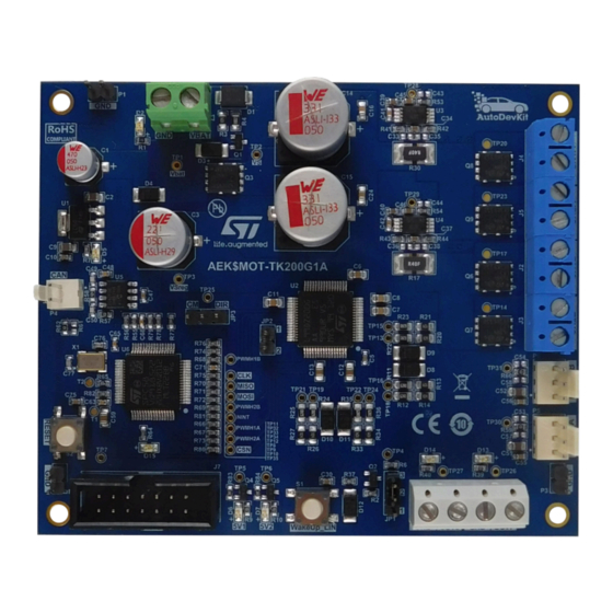
Figure 1.
L99DZ200G
chip. This safety feature is concurrent with all the other
switches off all the outputs and enters the fail-safe mode. The service key
AEK-MOT-TK200G1 evaluation board
UM2995
User manual
closing systems
L99DZ200G
www.st.com
Advertisement
Table of Contents

Related Manuals for ST AEK-MOT-TK200G1


Summary of Contents for ST AEK-MOT-TK200G1
-
Page 1: Figure 1. Aek-Mot-Tk200G1 Evaluation Board
• a CAN connector that allows a domain controller to interact remotely with the AEK-MOT-TK200G1. Moreover, to support DC motor positioning and increase actuation safety, a circuitry for the current sensing of the L99DZ200G H-bridges outputs has been added. -
Page 2: Hardware Overview
Connector for eventual Hall sensors JTAG connector for MCU programming 10. Connector for the two high-side outputs 11. Reset button 12. WakeUp_LIN button Figure 2. AEK-MOT-TK200G1 evaluation board: main components 1.1.1 SPC582B60E1 AEK-MOT-TK200G1 evaluation board hosts a Chorus 1M SPC582B60E1 microcontroller that belongs to the SPC58 Chorus family. -
Page 3: L99Dz200G
A/D conversion of supply voltages and internal temperature sensors Some of the L99DZ200G features are not implemented in the AEK-MOT-TK200G1: • On the board, we disabled the MCU programming via the LIN and CAN transceiver by connecting the LIN pin to Vsreg (12 V), while we left all the other pins related to CAN and LIN floating. To exit from a standby... -
Page 4: Current Sensing Monitoring Network
UM2995 Board main components Note: AEK-MOT-TK200G1 hosts an MCU that is always active as it is not powered by the L99DZ200G. Therefore, L99DZ200G standby status does not impact the MCU. Note: For further information on the L99DZ200G, see the related datasheet. -
Page 5: Can Connector And Potentiometer Connectors
1.1.4 CAN connector and potentiometer connectors AEK-MOT-TK200G1 additional features are: • A CAN connector for an external domain controller to drive the board via CAN messages, that is, to manage the opening/closing of the trunk. -
Page 6: L99Dz200G State Machine
UM2995 Board main components • The connectors for motor Hall sensor feedback. The sensors achieve an accurate motor positioning and increase the actuation reliability 1.1.5 L99DZ200G state machine As we are not using all the features of the L99DZ200G, the finite state machine (FSM) of the chip is simplified as shown below. -
Page 7: Watchdog Scheme
"late write" window. In case of watchdog failures, a reset signal is sent to the MCU. Figure 6. Watchdog timing 1 Note: For further details, refer to the L99DZ200G documentation on www.st.com. UM2995 - Rev 1 page 7/47 Arrow.com. Arrow.com. Arrow.com. -
Page 8: Software Overview
UM2995 Software overview Software overview AEK-MOT-TK200G1 software structure enhances reuse and simplifies maintenance. It also reduces the prototyping time. Thus, we have implemented a layered architecture that embeds the following blocks: • Low-level drivers • AEK_MOT_TK200G1_API The library is written in embedded C code. -
Page 9: Aek_Mot_Tk200G1_Api
• ADC: to convert the signal coming from the Hall sensors AEK_MOT_TK200G1_API The purpose of the API implemented is to expose all the functions of the AEK-MOT-TK200G1 board. The figure below shows the API functional blocks. Figure 9. API architecture... -
Page 10: Figure 10. Update Register Function
L99DZ200G features and significantly simplify the usage of the device by masking the information of the register details. • The wrapper functions expose at the AEK-MOT-TK200G1 level features (for example, motor driving) Figure 11. Wrapper functions Important: BOARD_STATUS_TYPE maps the current state of the board at runtime, while BOARD_CONFIG_TYPE stores the board configuration in the flash memory for a future use. -
Page 11: Safety Mechanism: Watchdog Trigger
Figure 12. Sel_mot_tk200g1_init() function Safety mechanism: watchdog trigger AEK-MOT-TK200G1 features a safety mechanism. The software portion of this safety mechanism includes a service key (that is, a watchdog) implemented with a programmable interrupt timer (PIT). When the PIT expires, a global state variable is updated through the interrupt associated callback. The value of this global variable is evaluated within each implemented API function. -
Page 12: Aek-Mot-Tk200G1 In Autodevkit
UM2995 AEK-MOT-TK200G1 in AutoDevKit AEK-MOT-TK200G1 in AutoDevKit The driver for the AEK-MOT-TK200G1 board is part of the AutoDevKit ecosystem. AutoDevKit component for the AEK-MOT-TK200G1 board has not been created, as the board hosts an MCU, and it is similar to a small ECU. -
Page 13: How To Locate The Aek-Mot-Tk200G1 Sw Library In The Demo
UM2995 How to locate the AEK-MOT-TK200G1 SW library in the demo Step 1. From the [Common task] panel, click on the [Import sample from application library] icon. Figure 13. Import sample from application library Step 2. In the Visual Studio Wizard, from the drop-down menu, select the family, the product, and the device. -
Page 14: How To Configure The Low-Level Drivers
Figure 16. Driver folders Step 3. To create from scratch a project that requires the AEK-MOT-TK200G1, copy the aek_mot_tk200g1_component_rla folder with all its content from a demo project and paste it under the source folder of the new project. How to configure the low-level drivers The configuration of the low-level drivers is mandatory. -
Page 15: Spi Configuration
PIT, and the names of the callback functions. Some of the key configurations are described in the following paragraphs. 3.4.1 SPI configuration To configure the SPI according to the AEK-MOT-TK200G1 hardware requirements, follow the procedure below. Step 1. Double-click on [DSPI and I2S Settings] in the [Outline] tab. Step 2. -
Page 16: Figure 19. Spi Configuration List
UM2995 How to configure the low-level drivers Step 3. In the [SPI configurations] section, click on the [+] button to add a row and configure the SPI port selected in the previous step. Figure 19. SPI configuration list Step 4. Double-click on the row just added. -
Page 17: Figure 21. Spi Timing Configuration
UM2995 How to configure the low-level drivers Step 6. In the [Timings] section, configure the baud rate for the L99DZ200G device. The values used in the demo are: – baud rate (bit/s): 250000 – tCSC(nsec): 4800 – tASC(nsec): 4800 – tDT(nsec): 1200 Figure 21. -
Page 18: Programmable Interrupt Timer (Pit) Configuration
AEK_MOT_TK200G1_TriggerWatchDog. Figure 23. PIT configuration 3.4.3 PWM configuration To drive the motors connected to the AEK-MOT-TK200G1 board with PWM signals, configure the eMIOS low- level driver. Step 1. Double-click on [eMios Settings] in the [Outline] tab. Step 2. Set the global prescaler in the [Internal Counter Frequency Settings] section. -
Page 19: How To Execute Sw Debug For The Aek-Mot-Tk200G1
UM2995 How to execute SW debug for the AEK-MOT-TK200G1 Step 3. In the [eMios Group0], select channels 2, 5, 6, and 7 as PWM. Figure 24. PWM configuration (1 of 3) Step 4. In the [PWM Configurations] section, click on the [+] button to add a row where to configure the PWM. -
Page 20: Figure 27. Debug Input Mode: Jumper Positioning
UM2995 How to execute SW debug for the AEK-MOT-TK200G1 Step 1. Insert a jumper in the JP2 connector. Figure 27. Debug input mode: jumper positioning Step 2. Connect the power supply to the J1 connector and power the board. Figure 28. -
Page 21: Figure 29. Debug Input Mode: Powering The Board
UM2995 How to execute SW debug for the AEK-MOT-TK200G1 Step 4. Connect the JTAG connector to the J7 connector and download the firmware with UDE PLS. Figure 29. Debug input mode: powering the board UM2995 - Rev 1 page 21/47 Arrow.com. -
Page 22: Available Demos For The Aek-Mot-Tk200G1
UM2995 Available demos for the AEK-MOT-TK200G1 Available demos for the AEK-MOT-TK200G1 The following demos with specific features are provided for the AEK-MOT-TK200G1 board: SPC582Bxx_RLA_AEK-MOT-TK200G1_MotorControl – Test Application for discovery SPC582Bxx_RLA_AEK-MOT-TK200G1_MotorControl_via_CAN – Test Application SPC58ECxx_RLA_MainECUFor_AEK-MOT-TK200G1Control – Test Application SPC582Bxx_RLA_AEK-MOT-TK200G1_MotorControl – Test Application for... - Page 23 UM2995 SPC58ECxx_RLA_MainECUFor_AEK-MOT-TK200G1Control – Test Application The CAN commands supported by the demo are defined in the CANCommunication.h file (path: source/ CANDriver/CANCommunication.h). UM2995 - Rev 1 page 23/47 Arrow.com. Arrow.com. Arrow.com. Arrow.com. Arrow.com. Arrow.com. Arrow.com. Arrow.com. Arrow.com. Arrow.com. Arrow.com. Arrow.com. Arrow.com. Arrow.com.
-
Page 24: Available Apis
UM2995 Available APIs Available APIs Table 2. Available APIs for the AEK-MOT-TK200G1 API name Description Initializes the driver and clears the AEK_MOT_TK200G1_Init() L99DZ200G status registers. Checks the validity of the global status byte AEK_MOT_TK200G1_CheckGlobalStatusByte() (GSB) Reads the ROM registers and returns the... - Page 25 UM2995 Available APIs API name Description Configuration register for the output current AEK_MOT_TK200G1_OutCurrMonitoring() monitoring Enables/disables the thermal expiration AEK_MOT_TK200G1_OutOCThExp() feature that protects the device when continuous auto-recovery events are triggered Sets the automatic Vs compensation for the AEK_MOT_TK200G1_AutomaticDCCOmpensationOdd() odd outputs (VLed settings) Sets the automatic Vs compensation for the AEK_MOT_TK200G1_AutomaticDCCOmpensationEven() even outputs (VLed settings)
-
Page 26: How To Customize The Current Sensing Network
How to customize the current sensing network How to customize the current sensing network The current sensing network implemented in the AEK-MOT-TK200G1 is designed to be used with the L12-50-100-12-P DC motor by Actuonix or a compatible one (see Section 1.1.3 To customize the current detection network for other DC motors, consider: •... - Page 27 UM2995 How to customize the current sensing network Step 6. Compute the gain of the current amplifier. The gain value must amplify the Vrsense input signal (the voltage across the Rsense resistor) so that the Vout maximum and minimum output voltages (output voltage of the opamp) is measurable via the ADC.
-
Page 28: Motor Model Used During The Aek-Mot-Tk200G1 Emission Tests
UM2995 Motor model used during the AEK-MOT-TK200G1 emission tests Motor model used during the AEK-MOT-TK200G1 emission tests The motors used during the tests are 413-0622 RS PRO. Table 3. Motor specifications Specification Value Voltage option 12 VDC Maximum input voltage... -
Page 29: Schematic Diagrams
Schematic diagrams Figure 31. AEK-MOT-TK200G1 circuit schematic (1 of 5) VSreg +5Vreg VBAT LD1117S50TR Vout GND/Adj Hole 3mm Hole 3mm Hole 3mm Hole 3mm LED Green, 3.2V 47uF 10uF 10uF 10nF BSS138 VBAT VSreg STTH3R02AFY SM6T36CAY 220uF 220nF L99DZ200GTR 220nF... -
Page 30: Figure 32. Aek-Mot-Tk200G1 Circuit Schematic (2 Of 5)
Figure 32. AEK-MOT-TK200G1 circuit schematic (2 of 5) Vp_B Vp_A 330uF 330uF 100nF 100nF 0.4R 0.4R Vm_B Vm_A STTH3R02AFY STTH3R02AFY STTH3R02AFY GH1B GH2B GH1A 100k 100k 100k SH1B SH2B SH1A 10nF 10nF 10nF 10nF GL1B GL2B GL1A 100k 100k 100k HB-B[1..6]... -
Page 31: Figure 33. Aek-Mot-Tk200G1 Circuit Schematic (3 Of 5)
Figure 33. AEK-MOT-TK200G1 circuit schematic (3 of 5) LED Blue, 3.2V 440R LED Blue, 3.2V 440R TP26 TP27 22nF 22nF OUT7 OUT7 MISO MOSI OUT8 OUT8 TP25 TxD_C CM/DIR RxD_C/NINT CAN_L Header 3x1 CAN_H OUT15 OUT14 VSreg TxD_L OUT3 RxD_L/NINT... -
Page 32: Figure 34. Aek-Mot-Tk200G1 Circuit Schematic (4 Of 5)
Figure 34. AEK-MOT-TK200G1 circuit schematic (4 of 5) +5Vreg +5Vreg R5522R Gain= 50 CAN2_TX STBY SEL1=Vcc R46 N.M. SEL2=Gnd CANH 100nF +5Vreg CANL +5Vreg +5Vreg CAN2_RX N.M. 47pF 47pF MCP2562FD-E_SN 100nF 100nF N.M. Vp_A 8TP2 Csensing_A 2.2uF 3 1K Vm_A TSC103IYPT N.M. -
Page 33: Figure 35. Aek-Mot-Tk200G1 Circuit Schematic (5 Of 5)
Figure 35. AEK-MOT-TK200G1 circuit schematic (5 of 5) PC2- CD/DIAG_A PWM1A PWMH1A PE10- CD/DIAG_B PWM2A PWMH2A +5Vmcu PWM1B NINT PWMH1B PWM2B PWMH2B NRES CAN2_TX CAN_TX PC1- Play/Mute CAN2_RX CAN_RX PORST NRESET PORST JCOMP PA5- JCOMP TESTMODE PA6- TCK PA7- TMS... -
Page 34: Bill Of Materials
UM2995 Bill of materials Bill of materials Table 4. AEK-MOT-TK200G1 bill of materials Item Q.ty Ref. Value Description Manufacturer Part Number 47uF, WCAP- Wurth SMD Electrolytic Capacitor 865080645012 ASLI_D6.3H7.7, 50 V, ±20 % Elektronik TAIYO 10uF, 0805C, 25 V, ±20 %... - Page 35 UM2995 Bill of materials Item Q.ty Ref. Value Description Manufacturer Part Number C33, C35, C36, C38, C43, SMD Ceramic Capacitor N.M., 0603C C44, (not mounted) C53, C54, C57, C34, 2.2uF, 0603C, 25 V, ±10 % SMD Ceramic Capacitor MURATA GRM188C71E225KE11D C39, C40, Wurth...
- Page 36 UM2995 Bill of materials Item Q.ty Ref. Value Description Manufacturer Part Number WL-SMCW SMT Mono- 150080YS75000, WL- color Chip LED Waterclear, Wurth 150080YS75000 SMCW_0805 size 0805, Yellow, 2V, Elektronik 140deg WR-TBL Serie 2135 Horizontal Entry Modular, Wurth 12V, 691213510002 691213510002 Rising Cage Clamp, pitch Elektronik 5.08mm, 2p...
- Page 37 UM2995 Bill of materials Item Q.ty Ref. Value Description Manufacturer Part Number R37, R53, R54, R64, R66, R67, R68, R69, 1k, 0603R, 1/8 W, ±1 % SMD Resistor PANASONIC ERJH3EF1001V R70, R71, R72, R73, R74, R75, R78, R79, R80, R81, R13, R14, R20,...
- Page 38 UM2995 Bill of materials Item Q.ty Ref. Value Description Manufacturer Part Number R41, R42, 10R, 0603R, 1/8 W, ±1 % SMD Resistor PANASONIC ERJH3EF10R0V R43, R45, R48, R49, R52, 0R, 0603R, 1/8 W, ±1 % SMD Resistor PANASONIC ERJH3G0R00V R57, R59, R60, R46,...
- Page 39 UM2995 Bill of materials Item Q.ty Ref. Value Description Manufacturer Part Number WR-WTB 2.54 mm Female Wurth 61900113722DEC 61900113722DEC Crimp Contact Elektronik WR-PHD 2.54mm Jumper Wurth 60900213421 60900213421 with Test Point Elektronik UM2995 - Rev 1 page 39/47 Arrow.com. Arrow.com. Arrow.com.
-
Page 40: Board Versions
PCB version Schematic diagrams Bill of materials AEK$MOT-TK200G1A AEK$MOT-TK200G1A schematic diagrams AEK$MOT-TK200G1A bill of materials 1. This code identifies the AEK-MOT-TK200G1 evaluation board first version. It is printed on the board PCB. UM2995 - Rev 1 page 40/47 Arrow.com. Arrow.com. Arrow.com. -
Page 41: Regulatory Compliance Information
UM2995 Regulatory compliance information Regulatory compliance information Formal Notice Required by the U.S. Federal Communications Commission FCC NOTICE This kit is designed to allow: (1) Product developers to evaluate electronic components, circuitry, or software associated with the kit to determine whether to incorporate such items in a finished product and (2) Software developers to write software applications for use with the end product. -
Page 42: Table 6. Document Revision History
UM2995 Revision history Table 6. Document revision history Date Revision Changes 17-May-2022 Initial release. UM2995 - Rev 1 page 42/47 Arrow.com. Arrow.com. Arrow.com. Arrow.com. Arrow.com. Arrow.com. Arrow.com. Arrow.com. Arrow.com. Arrow.com. Arrow.com. Arrow.com. Arrow.com. Arrow.com. Arrow.com. Arrow.com. Arrow.com. Arrow.com. Arrow.com. Arrow.com. Arrow.com. -
Page 43: Table Of Contents
PWM configuration ............18 How to execute SW debug for the AEK-MOT-TK200G1 ......19 Available demos for the AEK-MOT-TK200G1 . - Page 44 UM2995 Contents Revision history ...............42 List of tables .
- Page 45 Available APIs for the AEK-MOT-TK200G1 ........
- Page 46 AEK-MOT-TK200G1 evaluation board: main components ........
- Page 47 ST’s terms and conditions of sale in place at the time of order acknowledgment. Purchasers are solely responsible for the choice, selection, and use of ST products and ST assumes no liability for application assistance or the design of purchasers’...
Need help?
Do you have a question about the AEK-MOT-TK200G1 and is the answer not in the manual?
Questions and answers