Table of Contents
Advertisement
Quick Links
UM2451
User manual
How to use the AEKD-USBTYPEC1 USB Power Delivery evaluation kit
Introduction
The USB Power Delivery evaluation kit is designed to help you evaluate the functions of the USB Power Delivery protocol stack
implemented on the
SPC58EC80E5
Chorus line of 32-bit automotive microcontrollers based on Power Architecture®
technology, with 4 MB of flash memory.
You can also use the AEKD-USBTYPEC1 to prototype USB Power Delivery solutions to power compatible consumer devices
via the USB Type-C™ ports.
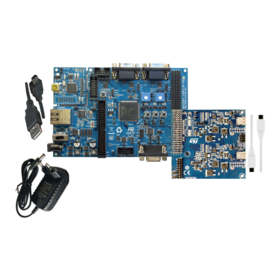
Figure 1.
AEKD-USBTYPEC1 USB Power Delivery evaluation kit
UM2451 - Rev 1 - August 2018
www.st.com
For further information contact your local STMicroelectronics sales office.
Advertisement
Table of Contents

Related Manuals for ST AEKD-USBTYPEC1


Summary of Contents for ST AEKD-USBTYPEC1
-
Page 1: Figure 1. Aekd-Usbtypec1 Usb Power Delivery Evaluation Kit
Chorus line of 32-bit automotive microcontrollers based on Power Architecture® technology, with 4 MB of flash memory. You can also use the AEKD-USBTYPEC1 to prototype USB Power Delivery solutions to power compatible consumer devices via the USB Type-C™ ports. Figure 1. -
Page 2: Evaluation Kit Overview
USB Type-C controller with Tx/Rx line driver and bi-phase marked coding (BMC), and the physical layer (PHY) protocol for USB Power Delivery stack. The AEKD-USBTYPEC1 kit supports a 5 V, 500 mA PDO based on the electrical characteristics of the SPC58EC- DISP. -
Page 3: Led Signals
UM2451 LED signals LED signals Figure 3. Port status LEDs on the AEK-USB-2TYPEC1 AEK-USB-2TYPEC1 interface board has the following status LEDs for each port: Role: emits a continuous variable blue flashing light at about 1Hz indicating the device is a provider. VBUS: emits a constant green light when the power negotiation has completed (i.e., the Explicit condition is reached). -
Page 4: How To Use The Aekd-Usbtypec1 Kit
UM2451 How to use the AEKD-USBTYPEC1 kit How to use the AEKD-USBTYPEC1 kit Step 1. Plug the AEK-USB-2TYPEC1 board on the SPC58EC-DISP AEK-USB-2TYPEC1 is plugged into the 4x37 male pin connector of the SPC58EC-DISP board via the 4x20 female pin connector from pins A18 to D37 (refer to pin numbering indications on the board). -
Page 5: Pin Mappings For An External Power Board
UM2451 Pin mappings for an external power board Power negotiation begins when the consumer is connected. If the negotiation concludes successfully (i.e., the “Explicit” condition is reached), the VBUS LED VBUS emits a green light. If the consumer has a compatible PDO but it is not able to reach the “Explicit” condition, try to: •... -
Page 6: Figure 6. Pin Mapping Of The Aek-Usb-2Typec1 Connectors
UM2451 Pin mappings for an external power board Figure 6. Pin mapping of the AEK-USB-2TYPEC1 connectors Connectors CN1 (4x20 male pin connector) and CN2 (2x9 male pin connector) are located on the opposite side of the USB Type-C ports. CN1 is for the control signals and CN2 is for the power supply. In the figure, the green cells in CN1 represent the pins to drive the external power board. -
Page 7: Table 2. Aek-Usb-2Typec1 4X20 Connector Power Board Pin Description
UM2451 Pin mappings for an external power board Pin Name Description LED12 To command the LED “VBUS” for port1 LED03 To command the LED “CC” for port0 LED13 To command the LED “CC” for port1 MISO_0 Master Input Slave Output (MISO) of SPI protocol for port 0 MISO_1 Master Input Slave Output (MISO) of SPI protocol for port 1 MOSI_0... - Page 8 UM2451 Pin mappings for an external power board Function[module instance] Pin name Port # GPIO ADC (12 bit) Timer SCK[2] CS0[6] G/P_12 PH[1] GPIO113 RX[3] RXD[6] UC15 SOUT[6] SIN[6] CS7[0] SIN[3] EXT_DEC0 SOUT[3] UC14 G/P_13 PD[12] GPIO60 ANS[15] TXD[14] SIN[4] UC16 ANF[15] SOUT[4]...
-
Page 9: Output Voltage Selection
UM2451 Pin mappings for an external power board 2.1.1 Output voltage selection The following table shows the 3-bit binary combinations to select specific output voltage levels for USB Type-C port0 and USB Type-C port1. The pins in the table are relative to the AEK-USB-2TYPEC1 board. -
Page 10: Software Package With Firmware And Usb Pd Project
Follow the procedure below to burn the code onto the flash memory of SPC58: Step 1. Download and install SPC5-UDESTK-SW USB/JTAG debugger from www.st.com Step 2. Connect the mini-B USB cable between your PC and the SPC58EC-DISP discovery board Step 3. -
Page 11: Figure 8. Help Menu In Spc5-Studio
UM2451 How to open the SPC5 Studio project Figure 8. Help menu in SPC5-Studio Step 4. Enter the text “USBPD” in the name field Step 5. Enter “usbpd.spc5studio.com” in the location field Figure 9. Install window in SPC5-Studio Step 6. Confirm the form Step 7. -
Page 12: Configuration Of The Usb-Pd Library Through Spc5-Studio
UM2451 Configuration of the USB-PD library through SPC5-Studio Configuration of the USB-PD library through SPC5-Studio After you download the package, you can open the project in SPC5-Studio and configure certain settings before you flash the firmware to the discovery board: Figure 10. -
Page 13: Figure 12. Hardware Crc, Led Signals, And Test Mode Toggles
UM2451 Configuration of the USB-PD library through SPC5-Studio • Enable or disable hardware CRC (enabled by default). If it is disabled, a software version is used. Figure 12. Hardware CRC, LED signals, and Test mode toggles • Enable or disable LED signals (enabled by default). •... -
Page 14: Figure 14. Spc58Ec-Disp Connected To Computer Via Usb Cable
UM2451 Configuration of the USB-PD library through SPC5-Studio Table 4. Default logic table for Port 0 and Port1 Vout_x [V] Port_sig1 Port_sig2 Port_sig3 If Test mode is enabled, you must connect a USB cable between the SPC58EC-DISP discovery board and your PC to print debug messages to a terminal window on your PC. -
Page 15: Usb Power Delivery Overview
UM2451 USB Power Delivery overview USB Power Delivery overview The USB Type-C and USB Power Delivery specifications allow smarter connectivity with fewer cables, less connectors and universal chargers. The Type-C connector supports all the features of previous standards, and ports can be configured to only supply power in a Provider role, only sink power in a Consumer role, or be able to switch between both in a Dual role. -
Page 16: St's Autodevkit Development Initiative
AutoDevKit for AEKD-USBTYPEC1 The AEKD-USBTYPEC1 evaluation kit consists of a discovery board (SPC58EC-DISP) and a USB Type-C dual port interface function board (AEK-USB-2TYPEC1). The 20x4 function board female connector on the function board is connected to the 4x37 male connector on the discovery board from the 18th pin to 37th pin. -
Page 17: Revision History
UM2451 Revision history Table 5. Document revision history Date Version Changes 26-Jul-2018 Initial release. UM2451 - Rev 1 page 17/22... -
Page 18: Table Of Contents
ST’s AutoDevKit development initiative ........ - Page 19 AEKD-USBTYPEC1 USB Power Delivery evaluation kit ........
- Page 20 AEKD-USBTYPEC1 kit terminology ........
-
Page 21: Table 6. Aekd-Usbtypec1 Kit Terminology
UM2451 Glossary Table 6. AEKD-USBTYPEC1 kit terminology Term Definition Power-data As per USB Power Delivery Specification, the PDO represents the format of data exchanged between object (PDO) provider and consumer to define the power capability in terms of output voltage and maximum current. - Page 22 ST’s terms and conditions of sale in place at the time of order acknowledgement. Purchasers are solely responsible for the choice, selection, and use of ST products and ST assumes no liability for application assistance or the design of Purchasers’...
Need help?
Do you have a question about the AEKD-USBTYPEC1 and is the answer not in the manual?
Questions and answers