Table of Contents
Advertisement
Quick Links
Getting started with the AEK-SNS-2TOFM1 evaluation board for car power
Introduction
The
AEK-SNS-2TOFM1
evaluation board offers an innovative approach based on Time-of-Flight (ToF) sensors for car power
liftgate applications.
This board represents a more cost-effective and reliable solution compared to the standard "kick under the bumper" solution.
The distance among the on-board sensors has been specifically designed for placement under the car bumper.
The kick gesture is replaced with a more unequivocal foot gesture interpreted by a finite state machine built in the
microcontroller firmware.
The board is designed as a small sensor hub ECU able to retrieve and process real-time sensor data to detect a gesture
performed under the two sensors. Moreover, you can control the board through an external domain controller via a CAN or a
serial interface.
Warning:
The
AEK-SNS-2TOFM1
inside a vehicle.
UM3006 - Rev 1 - May 2022
For further information contact your local STMicroelectronics sales office.
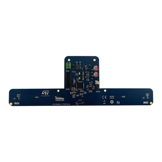
Figure 1.
AEK-SNS-2TOFM1 evaluation board
is an evaluation tool for R&D laboratory use only. It is not intended to be used
UM3006
User manual
liftgate applications
www.st.com
Advertisement
Table of Contents

Related Manuals for ST AEK-SNS-2TOFM1


Summary of Contents for ST AEK-SNS-2TOFM1
-
Page 1: Figure 1. Aek-Sns-2Tofm1 Evaluation Board
UM3006 User manual Getting started with the AEK-SNS-2TOFM1 evaluation board for car power liftgate applications Introduction AEK-SNS-2TOFM1 evaluation board offers an innovative approach based on Time-of-Flight (ToF) sensors for car power liftgate applications. This board represents a more cost-effective and reliable solution compared to the standard "kick under the bumper" solution. -
Page 2: Getting Started
AEK-SNS-2TOFM1 components (top view) The following figure shows the AEK-SNS-2TOFM1 bottom components: VL53L1X Time-of-Flight ranging sensor based on ST FlightSense technology Figure 3. AEK-SNS-2TOFM1 components (bottom view) The board hosts the SPC582B60E1 automotive microcontroller that belongs to the Chorus family, with a high performance e200z2 single core 32-bit CPU running at 80 MHz clock, a 1088 KB flash memory, and a 96 KB SRAM in a compact eTQFP64 package. -
Page 3: Software Overview
UM3006 Software overview Software overview AEK-SNS-2TOFM1 board contains a preloaded demonstration firmware. It is ready to be tested. If you have modified the flash memory code and you want to reinstall the original version, use the SPC5-UDESTK programmer plugged on the JTAG connector. The source code is included in AutoDevKit 1.6.1 (or higher). Among other demos, you can find one called “SPC582Bxx_RLA AEK_SNS_2TOFM1_1M_with_CAN_for_footdetection-... -
Page 4: Gesture Recognition
UM3006 Software overview 1.2.1 Gesture recognition The gesture consists in crossing the detection base (that is, the distance between the two ToF sensors) in both directions, as shown in the figure below. Figure 6. Gesture on the detection base The algorithm is based on the idea that the foot detection state can have one of the following values: •... -
Page 5: Figure 8. Accepted Sequence
UM3006 Software overview Figure 8. Accepted sequence The detect_foot () function, cyclically called by the microcontroller, implements the algorithm. The foot detection functions can be divided in: System State Detect that detects the state of the system: – if sensor 1 detects an object, the state becomes 1 –... -
Page 6: Basic Concepts On Flightsense Tof Sensors And Their Usage In Autodevkit
Figure 9. ToF principle According to the ToF principle, the sensors used in the AEK-SNS-2TOFM1 embed: • an emitter that is a vertical cavity surface emitting laser (VCSEL); •... -
Page 7: Vl53L1X
VL53L1X VL53L1X is a state-of-the-art, Time-of-Flight (ToF), laser-ranging sensor, enhancing the ST FlightSense product family. It is the fastest miniature ToF sensor on the market. It features an accurate ranging up to 4 m and fast ranging frequency up to 50 Hz. -
Page 8: Tof Sensor Characteristics
UM3006 VL53L1X 2.2.1 ToF sensor characteristics AEK-SNS-2TOFM1 sensor characteristics are: • a laser wavelength of 950 nm ± 30 nm; • invisible laser (Class 1); • invisible laser radiation; • a maximum laser power emission of 25 mW. 2.2.2 Laser safety considerations AEK-SNS-2TOFM1 ToF sensors contain a laser emitter and the corresponding drive circuitry. -
Page 9: Figure 13. Vl53L1X-Satel Top And Bottom Views
UM3006 VL53L1X Figure 13. VL53L1X-SATEL top and bottom views The embedded VL53L1X ToF sensor uses the I²C protocol for communication. The I²C bus on the VL53L1X has a maximum speed of 400 kbits/s and uses a default device address (0x52). You can connect the VL53L1X-SATEL to an MCU board through different connection types, as shown in the figure... -
Page 10: Power Up And Boot Sequence
UM3006 VL53L1X 2.2.4 Power up and boot sequence The ToF sensor has two different options for the power-up and boot sequence: • Option 1: the XSHUT pin is connected and controlled from the host. This option optimizes the power consumption as the sensor can be completely powered off when not used, and then woken-up again. The hardware standby mode is defined as the period when the power supply is present and the XSHUT is low. -
Page 11: Ranging Sequence
UM3006 AutoDevKit software library for ToF sensors 2.2.5 Ranging sequence The following figure shows the combination of the driver commands and the system states. Figure 17. Ranging sequence Power supply XShut GPIO1 (interrupt) Stop Start Clear Driver command rang. 1 rang. -
Page 12: Figure 18. Full Ranging Flow
UM3006 AutoDevKit software library for ToF sensors Figure 18. FULL ranging flow Figure 19. ULD ranging flow UM3006 - Rev 1 page 12/38... -
Page 13: How To Access The Aek_Sns_Vl53L1X1 Api
UM3006 How to access the AEK_SNS_VL53L1X1 API ULD API functions: VL53L1X_BootState VL53L1X_SensorInit Examples: VL53L1X_SetTimingBudget VL53L1X_SetOffset VL53L1X_StartRanging VL53L1X_CheckForDataReady Trigger GPIO1 pin VL53L1X_GetDistance VL53L1X_ClearInterrupt VL53L1X_StopRanging How to access the AEK_SNS_VL53L1X1 API To simplify API access, a struct(AEK_TOF_METHODS) method has been implemented in the AEK-SNS- VL53L1X1 component developed in the AutoDevKit. -
Page 14: Figure 21. Aek_Tof_Methods Full
UM3006 How to access the AEK_SNS_VL53L1X1 API Figure 21. AEK_TOF_METHODS FULL UM3006 - Rev 1 page 14/38... -
Page 15: Autodevkit Ecosystem
UM3006 AutoDevKit ecosystem AutoDevKit ecosystem AutoDevKit overview The application development employing the VL53L1X-SATEL industrial-grade ToF sensor board takes full advantage of the AutoDevKit ecosystem, whose basic components are: • SPC5-STUDIO integrated development environment (IDE) • SPC5-UDESTK debugger • STSW-AUTODEVKIT AutoDevKit software library •... -
Page 16: How To Create A Simple Aek-Sns-Vl53L1X1 Application
UM3006 How to create a simple AEK-SNS-VL53L1X1 application Finally, fill the main() function and build the target application. How to create a simple AEK-SNS-VL53L1X1 application This example allows you to create an application with one sensor. The goal is to detect an object when it is within a threshold that it is set between 50 and 150 millimeters. -
Page 17: Figure 23. Aek_Sns_Vl53L1X1 Component Configuration
UM3006 How to create a simple AEK-SNS-VL53L1X1 application Step 5. Click on the [Allocation] button below the AEK-SNS-VL53L1X1 list. Then, click [OK] in the confirmation window. This operation delegates automatic pin allocation to the AutoDevKit. Figure 23. AEK_SNS_VL53L1X1 component configuration 1. -
Page 18: Available Demos For Aek-Sns-Vl53L1X1
UM3006 Available demos for AEK-SNS-VL53L1X1 Step 10. Place the previous source code inside the main() function. #include “components.h” #include “AEK_SNS_VL53L1X1.h” int main(void) { VL53L1X_Result_t result; volatile uint8_t irq_state; /* Initialization of all the imported components in the order specified in the application wizard. - Page 19 SPC58ECxx_RLA AEK_SNS_VL53L1X1 - FULL Demo Double Sensor Ranging - Test Application In this demo, we use two AEK-SNS-2TOFM1 boards in polling mode with the FULL library. The boards have both the same settings. In this way, we can detect the objects in two different areas.
-
Page 20: How To Upload The Demos For Aek-Sns-2Tofm1
UM3006 How to upload the demos for AEK-SNS-2TOFM1 How to upload the demos for AEK-SNS-2TOFM1 Follow the procedure below to import the demos into SPC5-STUDIO. Step 1. Select [Import samples from application library] from the [Common tasks] panel. An import application wizard appears. -
Page 21: Available Uld Apis
UM3006 Available ULD APIs Available ULD APIs Note: For details on how to access the AEK_SNS_VL53L1X1 API, refer to Section 2.4 Table 2. List of available ULD APIs Name Description ULD_GetErrorSensorState(AEK_TOF_DEV Returns the sensor state index,AEK_TOF_ERROR *state) ULD_SetIRQSensorState(AEK_TOF_DEV index) Sets the IRQ variable ULD_GetIRQSensorState(AEK_TOF_DEV index, volatile Gets the IRQ variable uint8_t *state) - Page 22 UM3006 Available ULD APIs Name Description ULD_GetSignalPerSpad(AEK_TOF_DEV index, uint16_t Returns the returned signal per SPAD in *signalPerSp); kcps/SPAD ULD_GetAmbientPerSpad(AEK_TOF_DEV index, uint16_t Returns the ambient per SPAD in kcps/SPAD *amb); ULD_GetSignalRate(AEK_TOF_DEV index, uint16_t Returns the returned signal in kcps *signalRate); Returns the current number of enabled ULD_GetSpadNb(AEK_TOF_DEV index, uint16_t *spNb);...
- Page 23 UM3006 Available ULD APIs Name Description Performs the crosstalk calibration. It finds ULD_CalibrateXtalk(AEK_TOF_DEV index, uint16_t the crosstalk compensation value, applies TargetDistInMm, uint16_t *xtalk); the correction, and returns the crosstalk correction value UM3006 - Rev 1 page 23/38...
-
Page 24: Schematic Diagrams
Schematic diagrams Figure 26. AEK-SNS-2TOFM1 circuit schematic (1 of 5) U_PS-Regulator PS-Regulator.SchDoc Vbatt 12Vbatt 691213510002 U_CANplusSERIAL U_MCU U_ToF_Left-Right CAN-SERIAL.SchDoc MCU.SchDoc ToF_Left-Right.SchDoc TX_TTL TX_TTL RX_TTL RX_TTL Serial_TX-TTL Serial_TX-TTL I2C_SCL I2C_SCL Serial_RX-TTL Serial_RX-TTL I2C_SDA I2C_SDA Header-3pin XSHUT_L XSHUT_L XSHUT_R XSHUT_R CAN_H CAN_H... -
Page 25: Figure 27. Aek-Sns-2Tofm1 Circuit Schematic (2 Of 5)
Figure 27. AEK-SNS-2TOFM1 circuit schematic (2 of 5) LD39100PURY Transceiver_VL 10uF 100nF VOUT 2V8_L ToF_L 49K9 100nF 10uF 100nF 2V8_R ToF_R LD1117S50TR Vout GND/Adj 4.7uF 100nF 4.7uF 100nF 3V3_MCU 10nF 100pF STS10P4LLF6 LD1117S33TR 1SMB5929BT3G 12Vbatt Vout 4.7uH GND/Adj 10nF 100pF... -
Page 26: Figure 28. Aek-Sns-2Tofm1 Circuit Schematic (3 Of 5)
Figure 28. AEK-SNS-2TOFM1 circuit schematic (3 of 5) PH4- eMIOS_Ch19 PC2- CD/DIAG_A GPIO1_L PF2- eMIOS_Ch20 PE10- CD/DIAG_B XSHUT_R PD12- eMIOS_Ch14 Ind_Left_ToF Ind_Right_ToF Stand-by ToF PC3- HW Mute PI3- ADC39 PI4- ADC40 PC1- Play/Mute PORST PORST JCOMP 4.7K PA5- JCOMP TESTMODE... -
Page 27: Figure 29. Aek-Sns-2Tofm1 Circuit Schematic (4 Of 5)
Figure 29. AEK-SNS-2TOFM1 circuit schematic (4 of 5) N.M. 10uF 100nF 100pF CAN4-TX 60R4 CAN_H CAN_L 60R4 CAN4-RX L9616 4.7nF CAN - Interface Serial_TX-TTL TX_TTL RX_TTL Serial_RX-TTL SerialComunication - TTL_level... -
Page 28: Figure 30. Aek-Sns-2Tofm1 Circuit Schematic (5 Of 5)
Figure 30. AEK-SNS-2TOFM1 circuit schematic (5 of 5) N.M. N.M. 2V8_L 2V8_R XSHUT_L XSHUT_R XSHUT XSHUT GPIO1_LGPIO1_R GPIO1 AVDDVCSEL GPIO1 AVDDVCSEL AVDD AVDD AVSSVCSEL AVSSVCSEL 100pF GND2 100pF 100nF 4.7uF GND2 100nF 4.7uF GND3 GND3 GND4 GND4 VL53L1CXV0FY/1 VL53L1CXV0FY/1 LEFT... -
Page 29: Bill Of Materials
UM3006 Bill of materials Bill of materials Table 3. AEK-SNS-2TOFM1 bill of materials Item Q.ty Ref. Part/value Description Manufacturer Order code 10µF, 1206, 25 SMD ceramic C1, C4 Wurth Elektronik 885012208069 V, ±10% capacitors C2, C3, C5, C7, C9, C20, C21,... - Page 30 UM3006 Bill of materials Item Q.ty Ref. Part/value Description Manufacturer Order code WR-WTB THT, Male vertical pitch 2.54mm, Wurth Elektronik 61900211121 locking header WR-BHD THT, vertical, pitch Male box header Wurth Elektronik 61201421621 2.54 mm, 14 pins 5A, ±20% WE- LHMI SMT, size Power inductor Wurth Elektronik 74437349047...
- Page 31 - Chorus family Automotive high L9616, SO-8 speed can bus L9616 transceiver Time-of-Flight ranging sensor VL53L1CXV0FY U6, U7 based on ST VL53L1CXV0FY/1 /1, optical FlightSense technology 8-bit dual supply 1.71 V to 5.5 V ST2378ETTR, level translator ST2378ETTR TSSOP-20...
-
Page 32: Board Versions
AEK-SNS-2TOFM1 versions PCB version Schematic diagrams Bill of materials AEK$SNS-2TOFM1A AEK$SNS-2TOFM1A schematic diagrams AEK$SNS-2TOFM1A bill of materials 1. This code identifies the AEK-SNS-2TOFM1 evaluation board first version. It is printed on the board PCB. UM3006 - Rev 1 page 32/38... -
Page 33: Aek-Sns-2Tofm1 Regulatory Compliance Information
UM3006 AEK-SNS-2TOFM1 regulatory compliance information AEK-SNS-2TOFM1 regulatory compliance information Formal Notice Required by the U.S. Federal Communications Commission FCC NOTICE This kit is designed to allow: (1) Product developers to evaluate electronic components, circuitry, or software associated with the kit to determine whether to incorporate such items in a finished product and (2) Software developers to write software applications for use with the end product. -
Page 34: Revision History
UM3006 Revision history Table 5. Document revision history Date Revision Changes 24-May-2022 Initial release. UM3006 - Rev 1 page 34/38... -
Page 35: Table Of Contents
How to upload the demos for AEK-SNS-2TOFM1 ........ -
Page 36: List Of Tables
AEK-SNS-2TOFM1 bill of materials ........ -
Page 37: List Of Figures
AEK-SNS-2TOFM1 components (bottom view) ........ - Page 38 ST’s terms and conditions of sale in place at the time of order acknowledgment. Purchasers are solely responsible for the choice, selection, and use of ST products and ST assumes no liability for application assistance or the design of purchasers’...
Need help?
Do you have a question about the AEK-SNS-2TOFM1 and is the answer not in the manual?
Questions and answers