Sign In
Upload
Manuals
Brands
ST Manuals
Motherboard
AEK-POW-LDOV01S
ST AEK-POW-LDOV01S Manuals
Manuals and User Guides for ST AEK-POW-LDOV01S. We have
1
ST AEK-POW-LDOV01S manual available for free PDF download: User Manual
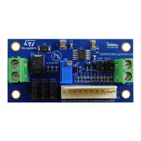
ST AEK-POW-LDOV01S User Manual (37 pages)
Automotive-grade LDOs with configurable output voltage
Brand:
ST
| Category:
Motherboard
| Size: 1 MB
Table of Contents
Figure 1. AEK-POW-LDOV01J Evaluation Board
1
Figure 2. AEK-POW-LDOV01S Evaluation Board
1
Figure 3. L99VR01JTR Functional Block
2
Figure 4. L99VR01STR Functional Block
2
Getting Started
3
Safety and Protection Mechanisms
3
MCU Connected Configuration
3
Standalone Configuration
3
Hardware Architecture
4
Table 1. CN1 Pin Description
4
Table 2. Jumper Pin Description
4
Table 3. Voltage Connector Details
4
Enable Pin
5
Figure 5. Enable and Disable Signals
5
Figure 6. Pulse Signal in Case of Output Voltage Changing
5
Output Voltage Selection
6
Watchdog (for the AEK-POW-LDO01J Only)
6
Table 4. Selx Pins: Truth Table
6
Table 5. WI Frequencies in Hz
6
Overvoltage Warning (for the AEK-POW-LDO01J Only)
7
Figure 7. Overvoltage Warning
7
Software Architecture
8
Spc5-Studio
8
Stsw-Autodevkit
8
AEK-POW-Ldov01X Software Library Architecture
8
Init Device
9
Power on
9
Figure 8. LDO Driver Finite State Machine
9
Power off
10
Setting the Output Voltage
10
Get Device Status
10
Get Warning Status
10
Get Output Voltage
10
Demo in the Autodevkit
11
How to Create a Sample Application for the AEK-POW-Ldov01X
11
Figure 9. [AEK-POW-Ldov01X Component RLA] Selection
11
Available Demos for the AEK-POW-Ldov01X
12
Figure 10. Adding a New Element
12
Figure 11. Voltage Regulator Selection
12
How to Upload the Demos
13
Figure 12. Demo Code
13
Figure 13. MCU Family Selection
14
Figure 14. Application Selection
14
Apis
15
Test Results
16
Figure 15. Enable Pulse Signal Waveform Generated by an External MCU Connected to the AEK-POW-LDOV01J
16
Figure 16. Watchdog Signal Waveform Generated by an External MCU Connected to the AEK-POW-LDOV01J
17
Figure 17. Output Voltage Waveform Generated by the AEK-POW-LDOV01J after Power on
18
Figure 18. Thermal Warning Waveform Generated by the AEK-POW-LDOV01J after Power on
19
Figure 19. Overvoltage Warning Waveform Generated by the AEK-POW-LDOV01J (Operating Voltage Selected = 5 V)
20
Figure 20. Reset Signal Waveform Generated by the AEK-POW-LDOV01J if the V O Output Voltage Is Lower than the V Th
21
AEK-POW-LDOV01J Schematic Diagrams
22
Figure 21. AEK-POW-LDOV01J Circuit Schematic
22
AEK-POW-LDOV01S Schematic Diagrams
23
Figure 22. AEK-POW-LDOV01S Circuit Schematic
23
AEK-POW-LDOV01J Bill of Materials
24
Table 6. AEK-POW-LDOV01J Bill of Materials
24
AEK-POW-LDOV01S Bill of Materials
26
Table 7. AEK-POW-LDOV01S Bill of Materials
26
AEK-POW-LDOV01J Versions
28
Table 8. AEK-POW-LDOV01J Versions
28
AEK-POW-LDOV01S Versions
29
Table 9. AEK-POW-LDOV01S Versions
29
AEK-POW-LDOV01J Regulatory Compliance Information
30
AEK-POW-LDOV01S Regulatory Compliance Information
31
Table 10. Document Revision History
32
Advertisement
Advertisement
Related Products
ST AEK-POW-LDOV01J
ST AEK-POW-BMSLV
ST AutoDevKit AEK-POW-BMS63EN
ST AEKD-USBTYPEC1
ST AEK-SNS-2TOFM1
ST AEKD-AICAR1
ST AEK-MOT-TK200G1
ST AEK-MOT-WINH92
ST AEK-COM-10BASET
ST AN3954
ST Categories
Motherboard
Computer Hardware
Microcontrollers
Control Unit
Controller
More ST Manuals
Login
Sign In
OR
Sign in with Facebook
Sign in with Google
Upload manual
Upload from disk
Upload from URL