Table of Contents
Advertisement
Quick Links
Series AP220 AcroPack
12-Bit Analog Output Module
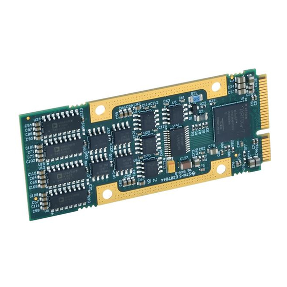
AP231 AcroPack
16-Bit High Density Analog Output Module
USER'S MANUAL
ACROMAG INCORPORATED
30765 South Wixom Road
Wixom, MI 48393-2417 U.S.A.
Tel: (248) 295-0310
Email: solutions@acromag.com
Copyright 2016, Acromag, Inc., Printed in the USA.
Data and specifications are subject to change without notice.
8501059G
Advertisement
Table of Contents

Subscribe to Our Youtube Channel
Related Manuals for Acromag AP220 AcroPack


Summary of Contents for Acromag AP220 AcroPack
- Page 1 16-Bit High Density Analog Output Module USER’S MANUAL ACROMAG INCORPORATED 30765 South Wixom Road Wixom, MI 48393-2417 U.S.A. Tel: (248) 295-0310 Email: solutions@acromag.com Copyright 2016, Acromag, Inc., Printed in the USA. Data and specifications are subject to change without notice. 8501059G...
-
Page 2: Table Of Contents
2.6 Functional Block diagram .................... 10 2.7 Field I/O Connector ....................11 Table 2.1 Field I/O Connector Pin Assignments ................11 68 PIN CHAMP CARRIER CONNECTOR ................. 11 Acromag, Inc. Tel: 248-295-0310 - 1 - - 1 - https://www.acromag.com http://www.acromag.com... - Page 3 4.1 Uncalibrated Performance ..................27 AP231 Model ..........................27 AP220 Model ..........................27 4.2 Calibrated Performance ....................28 AP231 Model ..........................28 AP220 Model ..........................28 Table 3.11 AP231 Model ......................29 Acromag, Inc. Tel: 248-295-0310 - 2 - - 2 - https://www.acromag.com http://www.acromag.com...
- Page 4 6.5 PCIe Bus Specifications ....................35 Table 6.5 PCIe Bus Data Rates ..................... 36 APPENDIX ..........................37 AP-CC-01 Heatsink Kit Installation ..................37 CERTIFICATE OF VOLATILITY ..................40 REVISION HISTORY ......................41 Acromag, Inc. Tel: 248-295-0310 - 3 - - 3 - https://www.acromag.com http://www.acromag.com...
-
Page 5: General Information
The information contained in this manual is subject to change without notice, and Acromag, Inc. (Acromag) does not guarantee its accuracy. Acromag makes no warranty of any kind with regard to this material, including, but not limited to, the implied warranties of merchantability and fitness for a particular purpose. -
Page 6: Ordering Information
+/-10 Volts, +/-5 Volts, +/-3 Volts, +/- 2.5V to 7.5 Volts • Reliable Software Calibration - Calibration coefficients stored on-board provide the means for accurate software calibration of the module. Acromag, Inc. Tel: 248-295-0310 - 5 - - 5 - https://www.acromag.com http://www.acromag.com... -
Page 7: Key Features Pcie Interface
Compatibility – PCI Express Base Specification v2.1 compliant PCI Express Endpoint. 1.4 Signal Interface Products This AcroPack Module will mate directly to all Acromag AP carriers. Once connected, the module is accessed via a front panel connector. The cables and termination panels are also available. For optimum performance with the AP231 analog output module, use of the shortest possible length of shielded I/O cable is recommended. -
Page 8: Windows
AcroPack modules, VPX I/O board products, and PCIe I/O Cards. The software is implemented as a library of “C” functions which link with existing user code to make possible simple control of all Acromag AcroPack modules. 1.6 References The following resources regarding AcroPack modules are available for download on Acromag’s website or by contacting your sales representative. -
Page 9: Preparation For Use
It is important that the user employ satisfactory overall system design. It is understood and agreed by the Buyer and Acromag that this is the Buyer's responsibility. -
Page 10: Installation Considerations
Refer to the specifications section for loading and power requirements. Be sure that the system power supplies are able to accommodate the power IMPORTANT: Adequate air requirements of the system boards, plus the installed Acromag board, circulation must be provided to within the voltage tolerances specified. -
Page 11: Functional Block Diagram
USER’S MANUAL SERIES AP220 / AP231 ACROPACK 2.6 Functional Block diagram Acromag, Inc. Tel: 248-295-0310 - 10 - - 10 - https://www.acromag.com http://www.acromag.com... -
Page 12: Field I/O Connector
Reserved/isolation Reserved/isolation CH1+ Signal Return Reserved/isolation Reserved/isolation CH2+ Signal Return Reserved/isolation Reserved/isolation CH3+ Signal Return Reserved/isolation Reserved/isolation CH4+ Signal Return Reserved/isolation Reserved/isolation CH5+ Signal Return Reserved/isolation Reserved/isolation CH6+ Acromag, Inc. Tel: 248-295-0310 - 11 - - 11 - https://www.acromag.com http://www.acromag.com... - Page 13 Reserved/isolation CH11+ Signal Return Reserved/isolation Reserved/isolation CH12+ Signal Return Reserved/isolation Reserved/isolation CH13+ Signal Return Reserved/isolation Reserved/isolation CH14+ Signal Return Reserved/isolation Reserved/isolation CH15+ Signal Return Reserved/isolation Reserved/isolation Reserved/isolation Reserved/isolation Acromag, Inc. Tel: 248-295-0310 - 12 - - 12 - https://www.acromag.com http://www.acromag.com...
-
Page 14: Logic Interface Connector
COEX1, COEX2 – wireless transmitter control are reassigned to JTAG signals TMS and TCK Lastly, UIM_C4, UIM_C8 – reserved User Identity Module signals are reassigned to JTAG signals TDI and TDO. Acromag, Inc. Tel: 248-295-0310 - 13 - - 13 - https://www.acromag.com... - Page 15 Note 2: +5V, +12V, and -12V power supplies have been assigned to pins that are reserved in the mini-PCIe specification. Note 3: All +3.3Vaux power pins are changed to +3.3V power. Note 4: The Present signal is tied to circuit common on the AP module. Acromag, Inc. Tel: 248-295-0310 - 14 - - 14 - https://www.acromag.com...
-
Page 16: Programming Information
Address Registers and the Interrupt Register which must be read to determine the base address assigned to the board and the interrupt request that goes active on a board interrupt request. Acromag, Inc. Tel: 248-295-0310 - 15 - - 15 - https://www.acromag.com... - Page 17 0x0000 0008 31:0 DAC Channel 0 0x0000 000C 31:0 DAC Channel 1 0x0000 0010 31:0 DAC Channel 2 0x0000 0014 31:0 DAC Channel 3 Acromag, Inc. Tel: 248-295-0310 - 16 - - 16 - https://www.acromag.com http://www.acromag.com...
-
Page 18: Module Location In System Register (Read Only) - (Bar0 + 0X0000 0004)
Not Used Module Location In System Register (Read Only) - (BAR0 + 0x0000 0004) This read only register is used identify the module’s plugin location in a system. Acromag, Inc. Tel: 248-295-0310 - 17 - - 17 - https://www.acromag.com http://www.acromag.com... -
Page 19: Dac Channel Registers (Read/Write) - (Bar0 + 0X0000 0008 To 0X0000 0044)
DAC data when issued of 0001 or 0011. Address 4-bits 0000 19 to 16 No Operation Write to input register (no DAC output update input 0001 register only written.) Used for simultaneous mode Acromag, Inc. Tel: 248-295-0310 - 18 - - 18 - https://www.acromag.com http://www.acromag.com... - Page 20 -5V to +5V 2 to 0 0V to +5V -2.5V to +7.5V -3V to +3V 0V to 16V (external power supply, contact Acromag) 0V to 20V (external power supply, contact Acromag) 2-bits Power-up Voltage Zero scale 4 to 3 Midscale...
-
Page 21: Output Data Format
Table 3.6 DAC Channel Data Format Straight Binary Decimal Code Twos Complement 1111 0111 1110 0110 1101 0101 1100 0100 1011 0011 1010 0010 Acromag, Inc. Tel: 248-295-0310 - 20 - - 20 - https://www.acromag.com http://www.acromag.com... -
Page 22: Transparent Mode
The Simultaneous Mode register must be written to first. Then, writing to the Simultaneous Output Trigger register creates the trigger for digital data to be converted and transferred to the board’s field connector. The digital Acromag, Inc. Tel: 248-295-0310 - 21 - - 21 - https://www.acromag.com... -
Page 23: Dac Write Status Register (Read Only) - (Bar0 + 0X0000 0054)
Trigger for a DAC output update. Otherwise, old data or unknown data present in the input latches will be transferred to the DAC output latch producing an undesired analog output. Acromag, Inc. Tel: 248-295-0310 - 22 - - 22 - https://www.acromag.com... -
Page 24: Xadc Status/Control Register (Read/Write) - (Bar0 + 0X0000 0088)
32-bit data transfers. The address value written to this register can be read on bits 22 to 16 of the XADC Status/Control register at BAR0 plus 0x48H. Acromag, Inc. Tel: 248-295-0310 - 23 - - 23 - https://www.acromag.com... -
Page 25: Firmware Revision Register (Read Only) - (Bar0 + 0X0000 0200)
Note that the Flash chip select must be set prior to the start of Flash memory instruction. Flash chip select must also be driven high after the instruction is issued. Acromag, Inc. Tel: 248-295-0310 - 24 - - 24 - https://www.acromag.com... -
Page 26: Flash Coefficient Memory Map
Channel 0 GainCoef MSB -3 to 3V 0x3F E014 Channel 0 OffsetCoef LSB -3 to 3V 0x3F E015 Channel 0 OffsetCoef MSB -3 to 3V 0x3F E016 Channel 0 GainCoef LSB Acromag, Inc. Tel: 248-295-0310 - 25 - - 25 - https://www.acromag.com http://www.acromag.com... -
Page 27: Use Of Calibration Data
Software calibration uses some fairly complex equations. Acromag provides software products (sold separately) to make communication with the board and calibration easy. It relieves you from having to turn the equations of the following sections into debugged software calibration code. -
Page 28: Uncalibrated Performance
Typically, each error component is much less than its maximum and all error components do not reinforce each other. Thus, typical errors are much less than that shown above. Acromag, Inc. Tel: 248-295-0310 - 27 - - 27 - https://www.acromag.com... -
Page 29: Calibrated Performance
(IdealCode) written to the 16-bit DAC to achieve a specified voltage within output range assuming Straight Binary (also called Bipolar Offset Binary) or 2’s Complement data format (see Table 3.11 and 3.12). Acromag, Inc. Tel: 248-295-0310 - 28 - - 28 - https://www.acromag.com... - Page 30 For applications needing better accuracy, the software calibration coefficients should be used to correct the IdealCode into the CorrectedCode required to accurately produce the output voltage. This is illustrated in equation (2): Acromag, Inc. Tel: 248-295-0310 - 29 - - 29 - https://www.acromag.com...
- Page 31 ActualZeroCode = Code1 − ( ActualSlope × ������������������1 ) Where: Code1 = 40 (0x28 hex) Code2 = 4055 (0xFD7 hex) Measured values (������������������2 ������ ������������������1)are taken using data averaging. Acromag, Inc. Tel: 248-295-0310 - 30 - - 30 - https://www.acromag.com http://www.acromag.com...
-
Page 32: Service And Repair
5.3 Where to Get Help If you continue to have problems, your next step should be to visit the Acromag worldwide web site at https://www.acromag.com. Our web site contains the most up-to-date product and software information. -
Page 33: Specifications
• AcroPack L x W: 70 mm x 30.00 mm (2.76 in x 1.18 in) Unit Weight (does not include shipping material): • AcroPack 0.016 lbs (0.0074 kg) Acromag, Inc. Tel: 248-295-0310 - 32 - - 32 - https://www.acromag.com http://www.acromag.com... -
Page 34: Power Requirements
AcroPack Heatsink Accessory AP-CC-01 and minimum airflow of 400LFM. For temperatures below 70°C the module will require a minimum airflow of 200LFM AP-CC-01 AcroPack Conduction Cool Kit (See Appendix for installation instructions) Acromag, Inc. Tel: 248-295-0310 - 33 - - 33 - https://www.acromag.com http://www.acromag.com... -
Page 35: Other Environmental Requirements
Conducted RF Immunity (CRFI), per IEC 61000-4-6. • Emissions per EN 61000-6-4: Enclosure Port, per CISPR 16. Low Voltage AC Mains Port, per CISPR 16. Note: This is a Class A product Acromag, Inc. Tel: 248-295-0310 - 34 - - 34 - https://www.acromag.com http://www.acromag.com... -
Page 36: Reliability Prediction
Compatibility Conforms to PCI Express Base Specification, Revision 2.1 Line Speed Gen1 (2.5Gbps) Available through front connector Lane Operation 1-Lane 4K Memory Space Required One Base Address Register Acromag, Inc. Tel: 248-295-0310 - 35 - - 35 - https://www.acromag.com http://www.acromag.com... - Page 37 Simple write operations are just as fast as DMA read operations. Write data is presented to the AcroPack in one transaction. Measured 4-byte back to back write accesses taking place every 100ns. Acromag, Inc. Tel: 248-295-0310 - 36 - - 36 - https://www.acromag.com...
-
Page 38: Appendix
AP-CC-01 Heatsink Kit Installation Hardware Bottom view Top view AP-CC-01 Heat Sink Kit This example will show how to install the AP-CC-01 Heatsink kit with an APCe7020 carrier. Acromag, Inc. Tel: 248-295-0310 - 37 - - 37 - https://www.acromag.com http://www.acromag.com... - Page 39 SERIES AP220 / AP231 ACROPACK 1. Install two standoffs and secure with two screws. 2. Install the AcroPack module. 3. Install the Heatsink and secure with 4 screws. Acromag, Inc. Tel: 248-295-0310 - 38 - - 38 - https://www.acromag.com http://www.acromag.com...
- Page 40 USER’S MANUAL SERIES AP220 / AP231 ACROPACK 4. AP-CC-01 Installation is complete. Note: Make sure the thermal pad is making contact with the FPGA IC. Acromag, Inc. Tel: 248-295-0310 - 39 - - 39 - https://www.acromag.com http://www.acromag.com...
-
Page 41: Certificate Of Volatility
Type(EEPROM, Flash, etc.) Size: User Modifiable Function: Process to Sanitize: □ Yes □ No Acromag Representative Name: Title: Email: Office Phone: Office Fax: Sales and solutions@acromag.com 248-295-0310 248-624-9234 Marketing Acromag, Inc. Tel: 248-295-0310 - 40 - - 40 - https://www.acromag.com http://www.acromag.com... -
Page 42: Revision History
LMP/ARP Add 68-pin Champ Connector to Table 2.1 04 DEC 2020 ENZ/AMM Updated MTBF Numbers. Removed “50-Pin” in reference to the Front Panel 10 MAR 2021 LMP/AMM Connector. Acromag, Inc. Tel: 248-295-0310 - 41 - - 41 - https://www.acromag.com http://www.acromag.com...
Need help?
Do you have a question about the AP220 AcroPack and is the answer not in the manual?
Questions and answers