Table of Contents
Advertisement
Quick Links
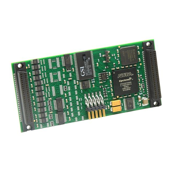
IOS-EP201/202/203/204 I/O Server Module
Cyclone II Based Reconfigurable FPGA
Digital I/O Modules
USER'S MANUAL
ACROMAG INCORPORATED
Tel: (248) 295-0310
30765 South Wixom Road
Fax: (248) 624-9234
P.O. BOX 437
Wixom, MI 48393-7037 U.S.A.
solutions@acromag.com
Copyright 2009-2011, Acromag, Inc., Printed in the USA.
8500-853-B11C007
Data and specifications are subject to change without notice.
Advertisement
Table of Contents

Related Manuals for Acromag IOS-EP201


Summary of Contents for Acromag IOS-EP201
- Page 1 USER’S MANUAL ACROMAG INCORPORATED Tel: (248) 295-0310 30765 South Wixom Road Fax: (248) 624-9234 P.O. BOX 437 Wixom, MI 48393-7037 U.S.A. solutions@acromag.com Copyright 2009-2011, Acromag, Inc., Printed in the USA. 8500-853-B11C007 Data and specifications are subject to change without notice.
-
Page 2: Table Of Contents
It is important that you perform satisfactory overall system design and it is agreed between you and Acromag, that this is your responsibility. 1.0 General Information KEY FEATURES…………...… …… …. … …… … …. . -
Page 3: Cyclone Ii Based Fpga Module
PUBLICATIONS IOS-EP2 FPGA Programming Guide Acromag IOS-EP2 EDK 71V016SA SRAM Specifications http://www.idt.com Cyclone II Data Book http://www.altera.com CY22150 Specification http://www.cypress.com IOS Specification http://www.vita.com ANSI/VITA 4-1995 Trademarks are the property of their respective owners. __________________________________________________________________________ Acromag, Inc. Tel:248-295-0310 Fax:248-624-9234 Email:solutions@acromag.com http://www.acromag.com... -
Page 4: General Information
RS485/RS422 Transceivers allow up to 32 nodes and up to 4000 feet of transmission cable. 64K x 16 SRAM – A 64K x 16 static random access memory (SRAM) is directly accessed by the Altera device. Custom user defined design __________________________________________________________________________ Acromag, Inc. Tel:248-295-0310 Fax:248-624-9234 Email:solutions@acromag.com http://www.acromag.com... -
Page 5: Ios Module Linux Software
This software (Model IOSSW-API-LNX) is composed of Linux libraries designed to support applications accessing I/O Server Modules installed on Acromag Industrial I/O Server systems The software is implemented as a library of “C” functions which link with existing user code __________________________________________________________________________ Acromag, Inc. -
Page 6: Preparation For Use
For repairs to a product damaged in shipment, refer to the Acromag Service Policy to obtain return instructions. It is suggested that salvageable shipping cartons and packing material be saved for future use in the event the product must be shipped. -
Page 7: Ios Field I/O Connector
I/O21+ I/O42 MAY DAMAGE THE I/O09+ I/O18 I/O21- I/O43 BOARD. I/O09- I/O19 I/O22+ I/O44 I/O10+ I/O20 I/O22- I/O45 I/O10- I/O21 I/O23+ I/O46 I/O11+ I/O22 I/O23- I/O47 I/O11- I/O23 External Clock Input I/O12+ I/O24 __________________________________________________________________________ Acromag, Inc. Tel:248-295-0310 Fax:248-624-9234 Email:solutions@acromag.com http://www.acromag.com... -
Page 8: Non-Isolation Considerations
I/O grounds. As such, the field I/O connections are not Considerations isolated from the system. Care should be taken in designing installations without isolation to avoid noise pickup and ground loops caused by multiple ground connections. __________________________________________________________________________ Acromag, Inc. Tel:248-295-0310 Fax:248-624-9234 Email:solutions@acromag.com http://www.acromag.com... -
Page 9: Programming Information
1. The IOS module will return 0 for all addresses that are Configuration Data Not Used “Not Used”. Register 2. The IOS module will not Not Acknowledged respond to read/write operations at these addresses. __________________________________________________________________________ Acromag, Inc. Tel:248-295-0310 Fax:248-624-9234 Email:solutions@acromag.com http://www.acromag.com... -
Page 10: Configuration Registers
JTAG interface will automatically over-write any existing configuration and can be completed at any time using a standard Altera JTAG download cable such as the ByteBlaster 2 . This cable is NOT provided by Acromag. Once again all programming is lost at power-down using the direct JTAG configuration approach. - Page 11 Cyclone II Based FPGA Module ___________________________________________________________________ An example program written in C and available from Acromag, implements configuration of the IOS-EP2 Series module over the IOS bus. The program requires the configuration file to be in the Intel Hex format. For information on generating hex files refer to the documentation supplied with the EDK.
-
Page 12: Ios Identification Space
In user mode, the ID space must be defined in the internal logic of the FPGA. In order for Acromag software to properly identify the model, this ID space must remain as defined in Table 3.2. Note that the base-address for the IOS module ID space (see your carrier board instructions) must be added to the addresses shown to properly access the ID information. -
Page 13: User Mode
The base address for the IOS module I/O space (see your carrier board instructions) must be added to the addresses shown in Table 3.3 to properly access the I/O space. Accesses can be performed on an 8-bit or 16-bit basis. __________________________________________________________________________ Acromag, Inc. Tel:248-295-0310 Fax:248-624-9234 Email:solutions@acromag.com http://www.acromag.com... -
Page 14: Control Register
Not Used Interrupt Vector Register Memory Data Register Memory Address Register Clock Control Register 1 Clock Control Register 2 Not Used Clock Control Register 3 Clock Generator Trigger Not Used Register Not Used __________________________________________________________________________ Acromag, Inc. Tel:248-295-0310 Fax:248-624-9234 Email:solutions@acromag.com http://www.acromag.com... - Page 15 Direction Control register. Note: if you select as an output port before setting this Input/Output register, the output port will be logic low as this is the power-up/reset state of the output register bits. __________________________________________________________________________ Acromag, Inc. Tel:248-295-0310 Fax:248-624-9234 Email:solutions@acromag.com http://www.acromag.com...
- Page 16 All not used bits will read low logic. See Table 2.1 for field I/O pin assignments corresponding to each of the Differential and TTL channels listed below. __________________________________________________________________________ Acromag, Inc. Tel:248-295-0310 Fax:248-624-9234 Email:solutions@acromag.com http://www.acromag.com...
- Page 17 Interrupt Polarity Register occurs (i.e. Low or High level transition interrupt). A “1” bit means the interrupt will occur when a Change-Of-State (COS) occurs at the __________________________________________________________________________ Acromag, Inc. Tel:248-295-0310 Fax:248-624-9234 Email:solutions@acromag.com http://www.acromag.com...
- Page 18 A “0” bit specifies that an interrupt will occur when the corresponding input channel is low (i.e. a “0” in the digital input channel data __________________________________________________________________________ Acromag, Inc. Tel:248-295-0310 Fax:248-624-9234 Email:solutions@acromag.com http://www.acromag.com...
- Page 19 Memory Address register need not be manually updated by software. Read or write accesses to this register require four wait states. A software or hardware reset has no affect on this register. __________________________________________________________________________ Acromag, Inc. Tel:248-295-0310 Fax:248-624-9234 Email:solutions@acromag.com http://www.acromag.com...
- Page 20 Cypress CY22150 Programmable Clock. The register contains the following control bits as specified in the Cypress CY22150 spec sheet. Data Data PB(0) PB(8) PB(1) PB(9) PB(2) Pump(0) PB(3) Pump(1) PB(4) Pump(2) PB(5) CLKSRC0 PB(6) CLKSRC1 PB(7) CLKSRC2 __________________________________________________________________________ Acromag, Inc. Tel:248-295-0310 Fax:248-624-9234 Email:solutions@acromag.com http://www.acromag.com...
-
Page 21: Clock Trigger Register
The program words required for Clock Control Register 1, 2, and 3 can be calculated using a program provided by Acromag (BitCalc2K1 Version 2) supplied with the EDK. Alternately, using the Clock Control Registers Data Maps and the CY22150 specification sheet the necessary values can be calculated. -
Page 22: Programming Interrupts
The Interrupt Input Response Time is specified in section 6. __________________________________________________________________________ Acromag, Inc. Tel:248-295-0310 Fax:248-624-9234 Email:solutions@acromag.com http://www.acromag.com... - Page 23 If the input stimulus is still applied, this will not clear the Interrupt Status Register bit and the interrupting channel(s) must remain disabled until the interrupt stimulus has been removed. After removal of the input stimulus the channel(s) may be cleared and re-enabled. __________________________________________________________________________ Acromag, Inc. Tel:248-295-0310 Fax:248-624-9234 Email:solutions@acromag.com http://www.acromag.com...
- Page 24 6. If the IOS module interrupt stimulus has been removed and no other IOS modules have interrupts pending, the interrupt cycle is completed (i.e. the carrier board negates its interrupt request INTA#). __________________________________________________________________________ Acromag, Inc. Tel:248-295-0310 Fax:248-624-9234 Email:solutions@acromag.com http://www.acromag.com...
-
Page 25: Theory Of Operation
As such, care must be taken to avoid ground loops. Ignoring this effect may cause operational errors, and with extreme abuse, possible circuit damage. __________________________________________________________________________ Acromag, Inc. Tel:248-295-0310 Fax:248-624-9234 Email:solutions@acromag.com http://www.acromag.com... -
Page 26: Field I/O
This input is not buffered and requires LVTTL signaling levels. Digital Input/Output Logic Digital TTL field I/O are provided on the IOS-EP201 and IOS-EP202 models through the Field I/O Connector (refer to Table 2.2). Digital input/output signals to the FPGA are buffered using an octal bus transceiver. -
Page 27: Jtag Interface
The clock frequency generated by the CY22150 is input to the FPGA on this pin. FPGA Pin Definitions The FPGA pin definitions are in the FPGA Programming Guide provided in the IOS-EP2 Series Engineering Design Kit. __________________________________________________________________________ Acromag, Inc. Tel:248-295-0310 Fax:248-624-9234 Email:solutions@acromag.com http://www.acromag.com... -
Page 28: Fpga Initialization
REPAIR repair. It is highly recommended that a non-functioning board be returned to Acromag for repair. The board can be easily damaged unless special SMT repair and service tools are used. Further, Acromag has automated test equipment that thoroughly checks the performance of each board. When a board is first produced and when any repair is made, it is tested, placed in a burn-in room at elevated temperature, and retested before shipment. -
Page 29: 6.0 Specifications
150KHz to 80MHz) and European Norm EN50082-1 with no register upsets. Electromagnetic Interference Immunity (EMI): No register upsets occur under the influence of EMI from switching solenoids, commutator motors, and drill motors. Surge Immunity: Not required for signal I/O per European Norm EN50082-1. __________________________________________________________________________ Acromag, Inc. Tel:248-295-0310 Fax:248-624-9234 Email:solutions@acromag.com http://www.acromag.com... -
Page 30: Board Components
Driver Input to Output Delay = 27ns Typical, 40ns Maximum Receiver Input to Output Delay = 33ns Typical, 60ns Maximum Termination Resistors Termination Resistors: Termination resistors are not provided. External 120 Ohm termination resistors for EIA RS485/422 differential receivers are recommended. __________________________________________________________________________ Acromag, Inc. Tel:248-295-0310 Fax:248-624-9234 Email:solutions@acromag.com http://www.acromag.com... -
Page 31: Digital Input/Output
IOS-EP2 I/O SERVER MODULE Cyclone II Based FPGA Module ___________________________________________________________________ DIGITAL TTL I/O TTL Channel Configuration: 48 Channels (IOS-EP201) or 24 Channels (IOS-EP203) of bi-directional TTL Transceivers Direction controlled in groups of eight. Reset/Power Up Condition: All Digital Channels Default to Input. -
Page 32: External Clock Input
FPGA from FLASH. During this time the board will act as if it is not configured until the download to the FPGA is complete. It is good practice to reset the board (using either an IOS bus or software reset) subsequent to power-up. __________________________________________________________________________ Acromag, Inc. Tel:248-295-0310 Fax:248-624-9234 Email:solutions@acromag.com http://www.acromag.com... -
Page 34: Jtag Interface/Jumper Location
IOS-EP2 I/O SERVER MODULE Cyclone II Based FPGA Module __________________________________________________________________ __________________________________________________________________________ Acromag, Inc. Tel:248-295-0310 Fax:248-624-9234 Email:solutions@acromag.com http://www.acromag.com...
Need help?
Do you have a question about the IOS-EP201 and is the answer not in the manual?
Questions and answers