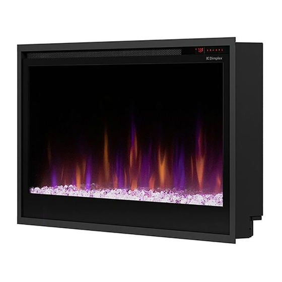
Table of Contents
Advertisement
Quick Links
IMPORTANT SAFETY INFORMATION:
Read this manual first before attempting to install or use this electric fireplace. Always comply with the
warnings and safety instructions contained in this manual to prevent personal injury or property damage.
7401150100R01
Service Manual
Models
PLF3614-XS - 6910470100
PLF4214-XS - 6910470200
PLF5014-XS - 6910470300
PLF6014-XS - 6910470400
Advertisement
Table of Contents

Subscribe to Our Youtube Channel
Summary of Contents for Dimplex PLF3614-XS
- Page 1 Service Manual Models PLF3614-XS - 6910470100 PLF4214-XS - 6910470200 PLF5014-XS - 6910470300 PLF6014-XS - 6910470400 IMPORTANT SAFETY INFORMATION: Read this manual first before attempting to install or use this electric fireplace. Always comply with the warnings and safety instructions contained in this manual to prevent personal injury or property damage.
-
Page 2: Table Of Contents
PLF3614-XS ........ -
Page 3: Exploded Parts Diagram
PLF6014-XS ....X-5904040400RP PLF3614-XS ......500002270 14. -
Page 4: Wiring Diagrams
Wiring Diagrams PLF3614-XS Flicker Motor Relay Board Power Supply Main Control Board Media Bed LEDs Flame LEDs PLF4214-XS Flicker Motor Relay Board Power Supply Main Control Board Media Bed LEDs Flame LEDs www.dimplex.com... -
Page 5: Plf5014-Xs
PLF5014-XS Flicker Motor Relay Board Power Supply Main Control Board Media Bed LEDs Flame LEDs PLF6014-XS Flicker Motor Relay Board Power Supply Main Control Board Media Bed LEDs Flame LEDs... -
Page 6: Replacement Part Procedures
6. Attach the suction cup to the mirrored glass to assist with removal. Ensure the seal is tight. 7. Tilt the mirrored glass and lift to remove it. Set it in a safe place for the duration of the service. (Figure 4) Figure 1 Figure 2 Figure 3 Figure 4 www.dimplex.com... -
Page 7: Heater Assembly Replacement
Heater Assembly Replacement Tools Required: Phillips Head Screwdriver Side Cutters Pliers 1. Follow the instructions for Preparing the Firebox for Service on page 6. 2. Remove the center rail (number of screws will vary by model.) (Figure 5) 3. Remove the 4 screws that hold the electronics cover panel. (Figure 5) 4. -
Page 8: Power Supply Replacement
8. Secure the wires previously bundled using one of the provided wire ties. 9. Position the new power supply and secure it using the previously removed power supply bracket. 10. Reinstall the electronics cover panel. 11. Reassemble the fireplace. Figure 7 Electronics Cover Panel Power Supply Bracket www.dimplex.com... -
Page 9: Main Control Board Replacement
Main Control Board Replacement Tools Required: Phillips Head Screwdriver CAUTION: Do not remove the conversion jumper from the new main control board. (Figure 9) The Heat Disable jumper should only be removed if a permanently heat-disabled installation is required. See owner’s manual for more information. -
Page 10: Hidden Touch Controls Replacement
If using the Flame Connect app, you will need to reconnect your fireplace to the app following replacement of the hidden touch controls. 15. Reassemble the unit. Figure 12 Figure 11 C-Channel L-Channel Insert screwdriver through QR Code Label semi-circle grooves to remove screws Figure 13 Figure 14 www.dimplex.com... -
Page 11: Relay Board Replacement
Relay Board Replacement Tools Required: Phillips Head Screwdriver Side Cutters 1. Follow the instructions for Preparing the Firebox for Service on page 6. 2. Remove the 4 screws that hold the electronics cover panel. (Figure 9, page 9) 3. Remove the screws that secure the L-channel (number of screws will vary by model). (Figure 11, page 10) 4. -
Page 12: Temperature Sensor (Ntc) Replacement
6. Secure the new NTC on the NTC bracket using the provided wire tie. 7. Secure the bracket using the 4 screws previously removed. 8. Reassemble the fireplace, ensuring the NTC wire is secured away from the mirrored glass when re-installing it. Figure 16 NTC Bracket www.dimplex.com... -
Page 13: Flicker Motor Replacement
Flicker Motor Replacement Tools Required: Phillips Head Screwdriver Side Cutters 1. Follow the instructions for Preparing the Firebox for Service on page 6. 2. Remove the 2 screws on each side of the bottom panel (4 total). Disconnect the LED connection, and set the bottom panel aside. -
Page 14: Flame Led Replacement
10. Secure the bottom panel, ensuring that the LED is reconnected through through the square opening. 11. Reassemble firebox. Figure 20 Remove left side last Pull rod outward Remove right side first Figure 21 Use pliers to pinch standoffs to allow for removal of LED board www.dimplex.com... -
Page 15: Media Led Replacement
Media LED Replacement Tools Required: Phillips Head Screwdriver 1. Follow the instructions for Preparing the Firebox for Service on page 6. 2. Remove the 2 screws on each side of the bottom panel (4 total). Disconnect the LED connection. (Figure 17, page 13) The media LED boards are located on the underside of the bottom panel. -
Page 16: Troubleshooting
Troubleshooting For more troubleshooting, consult the XLF-XD Service Manual which can be found at www.dimplex.com/customer_support/technical_and_troubleshooting Problem Display Cause Solution Ensure unit is wired correctly Fireplace does not turn on with No incoming power Check main disconnect panel the manual touch controls... - Page 17 Err 24 Main control board not detected disconected. Defective Main control board. Defective Display board. Err 25 Display board not detected Defective Main control board. For troubleshooting information related to the Flame Connect app, please visit www.dimplex.com/fcapp DATE ECO-000279 21-JUL-21 ECO-000441 24-MAY-22 1-888-346-7539 | www.dimplex.com...


Need help?
Do you have a question about the PLF3614-XS and is the answer not in the manual?
Questions and answers