
Related Manuals for Leuze BCL 8


Summary of Contents for Leuze BCL 8
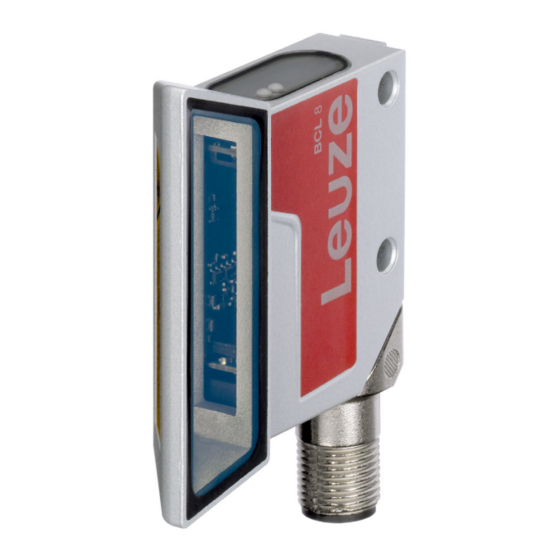
- Page 1 Original operating instructions BCL 8 Bar code reader with integrated decoder We reserve the right to make technical changes EN 2022-04-14 50127073...
- Page 2 © 2022 Leuze electronic GmbH + Co. KG In der Braike 1 D-73277 Owen / Germany Phone: +49 7021 573-0 Fax: +49 7021 573-199 http://www.leuze.com info@leuze.de Leuze electronic GmbH + Co. KG BCL 8...
-
Page 3: Table Of Contents
MA 8-01 - BCL - connecting the BCL 8 to the MA 8-01...... - Page 4 12.5 Example bar code label types ........... . . 63 Leuze electronic GmbH + Co. KG...
- Page 5 Dimensioned drawing BCL 8 S M …0, BCL 8 S N …0 with lateral beam exit......14 Figure 4.2: Dimensioned drawing BCL 8 S M …2, BCL 8 S N …2 with front beam exit ......15 Table 4.3: Type overview - M optics ......................16 Table 4.4:...
-
Page 6: General Information
NOTE This symbol indicates text passages containing important information. Declaration of Conformity The BCL 8 bar code reader and the optional MA 8.1 connection unit have been developed and produced in accordance with the applicable European standards and directives. NOTE The corresponding declaration of conformity can be requested from the manufacturer. -
Page 7: Safety
Intended use The BCL 8 bar code reader is designed as a stationary scanner with integrated decoder for all common bar codes used for automatic object detection. The optional MA 8.1 connection unit is intended for the easy connection of a bar code reader of type BCL 8. -
Page 8: Foreseeable Misuse
V3 (e.g. electrician foreman). In other countries, there are respective regulations that must be observed. Exemption of liability Leuze electronic GmbH + Co. KG is not liable in the following cases: • The device is not being used properly. • Reasonably foreseeable misuse is not taken into account. - Page 9 Safety BCL 8 S …2 BCL 8 S …0 A Laser aperture B Laser warning sign Figure 2.1: Laser apertures, laser warning signs Leuze electronic GmbH + Co. KG BCL 8...
-
Page 10: Description
The many possible configurations of the device allow it to be adapted to a multitude of reading tasks. Due to the small dimensions of the unit and its large reading field, the BCL 8 may also be used in highly constrained spaces. - Page 11 Description Ideally, all BCL 8 devices are to be connected to one another with MA 8.1 connection units so that: • the voltage supply of the BCL 8/MA 8.1 is ensured. • TxD to RxD of the RS 232 is established from one BCL 8 to the next (host).
-
Page 12: Technical Data
Metal (diecast zinc) Environmental data Ambient temp. (operation/storage) 0°C … +40°C/-20°C … +60°C Air humidity Max. 90% rel. humidity, non-condensing Vibration IEC 60068-2-6, test Fc Shock IEC 60068-2-27, test Ea Table 4.1: Technical data Leuze electronic GmbH + Co. KG BCL 8... -
Page 13: Led Indicators
Red, continuous Error, no function Orange, flashing Service operation (200 ms) Decode Green (200ms on) Reading successful Red (200ms off) No read result Orange, continuous Reading gate active Table 4.2: LED indicators Leuze electronic GmbH + Co. KG BCL 8... -
Page 14: Dimensioned And Connection Drawings
Indicator LEDs (B1: status LED, B2: decode LED) Scanning beam, divergence max. 5mm at 150 mm reading distance Optical axis Figure 4.1: Dimensioned drawing BCL 8 S M …0, BCL 8 S N …0 with lateral beam exit Leuze electronic GmbH + Co. KG BCL 8... - Page 15 Indicator diodes (B1: status LED, B2: decode LED) Scanning beam, divergence max. 5mm at 150 mm reading distance Optical axis Figure 4.2: Dimensioned drawing BCL 8 S M …2, BCL 8 S N …2 with front beam exit Leuze electronic GmbH + Co. KG BCL 8...
-
Page 16: Optical Data
Therefore, when selecting a mounting location and/or the bar code label, take into account the different reading characteristics of the scanner with various bar code modules. For different reading task and connection requirements, the BCL 8 is available in various models (see chapter 4.4.1 "Type overview"). 4.4.1... - Page 17 90 100 110 120 130 140 150 160 170 Distance in mm Front beam exit Figure 4.3: Reading field of BCL 8 S M … with M optics (medium density) Reading field of BCL 8 with N optics Code 2/5 int. Lateral beam Ratio 1:2.5 exit Class A acc.
-
Page 18: Accessories/Order Codes
Accessories overview Designation Part no. Short description MA 8.1 50101699 MA 8.1 connection unit for BCL 8, RS 232 point-to-point connection, 1 switching input and 1 switching output, 24V DC MA 8-01 50104790 MA 8-01 connection unit for BCL 8,... -
Page 19: Ma 8.1 Connection Unit
Accessories/order codes MA 8.1 connection unit The MA 8.1 connection unit is used to simplify the electrical installation of the BCL 8. The connection unit offers the following advantages over the installation of the BCL 8 as a stand-alone device: •... -
Page 20: Electrical Connection Ma 8.1
PWR IN HOST/RS232 (5-pin connector, A-coded) Name Comment Positive supply voltage: +10 … +30VDC RS 232 transmit data from the BCL 8 to the host Supply voltage: 0VDC PWR IN RS 232 receive data from the host to the BCL 8... -
Page 21: Ma 8.1 - Sw In/Out - Switching Input And Switching Output
The MA 8.1 is provided with a switching input and a switching output. The connection of switching input / switching output is carried out in accordance with Figure 5.5. Switching input Switching output Figure 5.5: Connection of the switching input/output of the MA 8.1 Leuze electronic GmbH + Co. KG BCL 8... -
Page 22: Ma 8.1 - Bcl - Connecting The Bcl 8 To The Ma 8.1
Degree of protection IP 67 is achieved only if the connectors and caps are screwed into place! The BCL 8 is connected to the MA 8.1 via the connection cable KB 008-1000/2000/3000 (AA/AR). The voltage supply is connected via the PWR IN HOST/RS232 socket. -
Page 23: Connection Unit Ma 8-01
Connection unit MA 8-01 The modular connection unit is an optional accessory when connecting a BCL 8 to an RS 485 interface. The RS 485 interface, the switching input and the switching output are all connected to the MA 8-01. It also supplies voltage to the BCL 8. -
Page 24: Ma 8-01 - Pwr In Host/Rs485 - Voltage Supply And Rs 485
2 is not assigned. Otherwise, the switching output is not protected against feedback on the switching input. If the inverted sensor output lies on pin 2, erroneous behavior of the switching output will result. Leuze electronic GmbH + Co. KG BCL 8... -
Page 25: Ma 8-01 - Bcl - Connecting The Bcl 8 To The Ma 8-01
Degree of protection IP 67 is achieved only if the connectors and caps are screwed into place! The BCL 8 is connected to the MA 8-01 via the connection cable KB 008-1000/2000/3000 (AA/AR). The voltage supply is connected via the PWR IN HOST/RS485 socket. -
Page 26: Termination Of The Rs 485 Interface
Figure 5.12: Termination of the RS 485 interface in the MA 8-01 Mounting accessories A variety of mounting devices are available for mounting the BCL 8. These are designed for rod or screw mounting (see also the Leuze Catalog, Series 8 Accessories). -
Page 27: Installation
Observe the applicable local regulations when disposing of the packaging materials. Cleaning Clean the glass window of the BCL 8 with a soft cloth before mounting. Remove all packaging remains, e.g. carton fibers or Styrofoam balls. ATTENTION! Do not use aggressive cleaning agents such as thinner or acetone for cleaning the device. -
Page 28: Device Arrangement
NOTE With front beam exit, the beam exit on the BCL 8 is nearly vertical to the reading window; with lateral beam exit, the beam exit is at 15° from vertical. The bar code label must be rotated by >... -
Page 29: Connecting
Connection of the device and maintenance work while under voltage must only be carried out by a qualified electrician. The power supply unit for the generation of the supply voltage for the BCL 8 and the corre- sponding connection units must have a secure electrical insulation according to IEC 60742 (PELV). - Page 30 Figure 6.6: Switching output BCL 8 ATTENTION! Do not load the respective switching output of the BCL 8 with more than 20mA at +5 … 30VDC! NOTE You can configure the switching input/switching output according to your requirements using the Sensor Studio program.
-
Page 31: Cable Lengths
Table 6.2: Cable lengths NOTE The RS 232 connection between BCL 8 and host must not exceed a total of 10m. Disassembling, packing, disposing Repacking For later re-use, the device is to be packed so that it is protected against shocks and humidity. Optimum protection is achieved when using the original packaging. -
Page 32: Commissioning
After connecting the operating voltage, the BCL 8 performs an automatic "Power On" function test. After- ward, the green status LED on the top side of the BCL 8 lights up. Only then are any saved customer- specific settings active. -
Page 33: Service Operating Mode
Connecting You can connect a PC or a terminal to the BCL 8 via the serial interface and configure the BCL 8 through this connection. The connection is made using an RS 232 connection cable that establishes the RxD, TxD and GND connections between PC and BCL 8. -
Page 34: Operation
NoRead character is transmitted at the end of the reading gate). Display elements On the BCL 8, you will find two LEDs that show the operational readiness and the reading state of the bar code reader (see Table 4.2 on page 13). -
Page 35: Configuration And Diagnostics Software - Sensor Studio
Communication and device DTMs are included in the installation package. Sensor Studio Create the device DTM for BCL 8 in the project tree of the FDT frame. Connect the bar code reader to the PC (see chapter "Connecting"). -
Page 36: Installing Sensor Studio
NOTE Sensor Studio The installation files of the configuration software must be downloaded from the Internet at www.leuze.com. For subsequent updates, you can find the most recent version of the Sensor Studio installation software on the Internet at www.leuze.com. 9.2.1 Downloading configuration software ... - Page 37 The project wizard displays the device selection list of the configurable devices. Figure 9.1: Device selection for the BCL 8 Select BCL 8 in the device selection and click [Next]. The device manager (DTM) of the connected bar code reader starts with the offline view for the Sensor Studio configuration project.
-
Page 38: Exiting Sensor Studio
• : [Reset all parameters in the GUI to their factory default settings] Resets all parameters in the graphical user interface to the factory settings. 9.5.1 Decode tab Figure 9.3: Decode tab Leuze electronic GmbH + Co. KG BCL 8... - Page 39 Alternatively, you can select the property settings directly via the navigation tree with the [Symbologies] button. The properties can be individually set for each code type. Figure 9.4: Standard settings of the Properties dialog box (SYMBOLOGY PROPERTIES) Leuze electronic GmbH + Co. KG BCL 8...
- Page 40 Identical labels are treated as a single label. NOTE In general, the remaining parameters must not be changed. In the worst case, this could corrupt the read result! Leuze electronic GmbH + Co. KG BCL 8...
-
Page 41: Output Tab
This character is set for each unrecognized bar code. Multiple characters (=string) may be entered here. Up to 20 characters are (No read string) possible. Properties dialog box (Common Properties) Set the desired formatting modes and formatting characters as necessary. Leuze electronic GmbH + Co. KG BCL 8... - Page 42 Output different result only checkbox is selected. The timeout time between the last reading and deletion of the difference memory can be set from 100 ms to 5000 ms. Leuze electronic GmbH + Co. KG BCL 8...
-
Page 43: Control Tab
(e.g. for test purposes). Scans without info Following a successful read, the code reader waits for this number of scans (sequential scans with no read result) before it automatically deactivates itself. Leuze electronic GmbH + Co. KG BCL 8... -
Page 44: Host Interface Tab
To be able to continue to communicate with a device following a parameter transfer, you may need to make appropriate adjustments to the communication properties of the device in the Sensor Studio configuration software. Leuze electronic GmbH + Co. KG BCL 8... -
Page 45: Reference Code Tab
Contents of the reference code. (Info) Comparison mode Select here how the internally stored reference code is to be compared with the decoded result. For additional comparison possibilities, select the Properties dialog box. Leuze electronic GmbH + Co. KG BCL 8... -
Page 46: Switching Input Tab
Here, the input level can be inverted Debounce time This time period must lapse until the trigger signal is regarded as valid. Switch-on delay time The trigger signal is passed on delayed by the specified time period. Leuze electronic GmbH + Co. KG BCL 8... -
Page 47: Switch Tab
Multiple events can also be simultaneously activated. Inverted Here, the input level can be inverted Pulse duration Duration of the switching output pulse. Pulse delay time Length of time before the switching output is activated. Leuze electronic GmbH + Co. KG BCL 8... -
Page 48: Diagnosis
NOTE Firmware Reload You can find detailed information on the tool in the information area of the Sensor Studio FIRMWARE RELOAD dialog box and in the online help. Leuze electronic GmbH + Co. KG BCL 8... - Page 49 • If the new firmware is compatible, the firmware is automatically installed in the device. • If the new firmware is not compatible with the device or is identical with the current firmware ver- sion, a dialog box for canceling or continuing the installation is displayed. Leuze electronic GmbH + Co. KG BCL 8...
-
Page 50: Starting Up The Device - Configuration
12.3 "Diagnostics and troubleshooting". If a problem occurs that cannot be rectified even after checking all electrical connections and settings on the devices and on the host, contact your responsible Leuze subsidiary or Leuze customer service (see chapter 12.4 "Service and support"). -
Page 51: Setting The Configuration Parameters
• Prefix: STX • Postfix: CR, LF Activate service interface The service interface can be activated by holding a defined bar code label in front of the reading window during power-up (initialization phase). Leuze electronic GmbH + Co. KG BCL 8... -
Page 52: 10.4.2 Parameter Sets
• Copying a valid parameter set from the host computer into the bar code reader Sensor Studio • Off-line configuration using the configuration software and then subsequently loading to the bar code reader NOTE To load the configuration into the bar code reader, select online mode. Leuze electronic GmbH + Co. KG BCL 8... -
Page 53: Online Commands
Commands, command parameters and returned data are enclosed between single quotation marks ’ ’ in the text of this manual. Most online commands are acknowledged by the BCL 8 and any requested data returned. For commands that are not acknowledged, command execution can be observed or monitored directly on the device. - Page 54 ’CA’ Description Activates or deactivates the ’autoConfig’ function. Certain label reading parameters are programmed automatically in the setup by the labels which the BCL 8 reads while the 'autoConfig' function is active. ’+’ Activates ’autoConfig’ Parameter ’/’ Rejects the last code read ’-’...
- Page 55 ’RS’ Description This command can be used to define a new reference code in the BCL 8 by means of direct input via the serial interface. The data is saved in the param- eter set according to your input under reference code 1 or 2 and stored in the working buffer for direct further processing.
- Page 56 ’RTy’ command. Reading a reference code Command ’RR’ Description The command reads out the reference code defined in the BCL 8. If no parameters are specified, all defined codes are output. Parameter <Reference code number> ’1’ Reference code 1 ’2’...
-
Page 57: 11.1.2 Online Commands For System Control
Switching output No. ’1’ (output 1) Acknowledgment None Deactivate switching output Command ’OD’ Description The command deactivates a selected switching output. ’ODx’: Deactivate switching output Parameter Switching output No. ’1’ (output 1) Acknowledgment None Leuze electronic GmbH + Co. KG BCL 8... -
Page 58: 11.1.3 'Online' Commands For Parameter Set Operations
• <Para0L> <Para0H>… <Para122L> <Para122H>: Parameter set data of the message. The sequence of the data is arranged identically to the BCL 8, i.e. when a word is transmitted, first the low byte is sent then the high byte. The parameter set data is converted for transmission from HEX format to a 2-byte-ASCII format. - Page 59 Request parameter set from the BCL 8 Command ’PR’ Description The command requests parameter data from the BCL 8. The <PS type> parameter indicates from which parameter set the data are to be transferred Parameter <BCC type> <PS type> <Start address> <Data length>...
- Page 60 '8' invalid parameter set '9' invalid parameter set type Example ’PT03203305’ Address 33 (equal scans) is set to 5. Save in RAM with reset (immediate acceptance of the change and temporary storage) Leuze electronic GmbH + Co. KG BCL 8...
-
Page 61: Maintenance
Usually, the BCL 8 bar code reader does not require any maintenance by the operator. Cleaning Should it become soiled, clean the glass window of the BCL 8 with a soft cloth. NOTE Do not use aggressive cleaning agents such as thinner or acetone for cleaning the device. -
Page 62: Service And Support
12.4 Service and support Service hotline You can find the contact information for the hotline in your country on our website www.leuze.com under Contact & Support. Repair service and returns Defective devices are repaired in our service centers competently and quickly. We offer you an extensive service packet to keep any system downtimes to a minimum. -
Page 63: Example Bar Code Label Types
Code type 11: Codabar Module 0.3 Code 128 Module 0.3 Code type 10: EAN 13 Add-on SC 0 Code type 08: EAN 128 Module 0.3 Figure 12.1: Example bar code label types Leuze electronic GmbH + Co. KG BCL 8...
Need help?
Do you have a question about the BCL 8 and is the answer not in the manual?
Questions and answers