
Related Manuals for Leuze BCL 40


Summary of Contents for Leuze BCL 40
- Page 1 Leuze electronic Bar Code Reader BCL 40 with Integrated Decoder Connector Unit MA 10 Technical Description Buy: www.ValinOnline.com | Phone 844-385-3099 | Email: CustomerService@valin.com...
- Page 2 © All rights reserved, especially the right of reproduction and translation. Duplication or reproduction in any form may only be carried out with the expressed written consent of Leuze electronic GmbH & Co. We reserve the right to make changes for the technical improvement of the product.
-
Page 3: Table Of Contents
Safety Notices ........................8 Safety Standards ......................... 8 Intended Use........................8 Working Safely ........................9 Description ........................10 The Bar Code Readers BCL 40 ..................10 Features of the BCL 40 ...................... 10 3.2.1 Performance features ........................10 3.2.2 Added features with MA 10......................11 3.2.3... - Page 4 Table of contents 6.3.1 Connecting the BCL 40 for "Stand Alone" Operation ..............38 6.3.2 Connecting the BCL 40 with the connector unit MA 10..............40 6.3.3 Wire Lengths and Shielding ......................50 Disassembling, Packing, Disposing ................... 50 Commissioning ........................ 51 Measures to be performed prior to the first commissioning ..........51 Function Test ........................
- Page 5 Figure 4.5: Sweep principle for the line scanner ................22 Figure 4.6: Reading curves BCL 40 standard version, optic variants N and M ......23 Figure 4.7: Reading curves BCL 40 standard version, optic variants F and L ......24 Figure 4.8:...
- Page 6 Figure 9.11: "Switch 1" menu, standard setting................72 Table 11.1: ASCII Table ........................ 87 Figure 11.1: Bar code sample labels (module width 0.3) ............... 88 Figure 11.2: Bar code sample labels (module 0.5)................. 89 BCL 40 Leuze electronic Buy: www.ValinOnline.com | Phone 844-385-3099 | Email: CustomerService@valin.com...
-
Page 7: General Information
The microprocessor control unit which translates the scanned bar code information into a simple signal that can be processed further. Frame protocol Transfer protocol for the data transfer between the bar code reader and the host. Leuze electronic BCL 40 Buy: www.ValinOnline.com | Phone 844-385-3099 | Email: CustomerService@valin.com... - Page 8 (e.g. RS 232, RS 422, etc.). Label Barcode label multiNet The network developed by Leuze for networking together several bar code readers. No Read Read failure; a read process was initiated but a label could not be decoded. Online command A command which is sent directly to the bar code reader from the host or a computer connected to the interface.
-
Page 9: Declaration Of Conformity
Teach-In Programming a reference code using an example bar code. Declaration of Conformity The bar code readers BCL 40 and the connector unit MA 10 have been developed and produced in accordance with the applicable European standards and directives. Notice! The corresponding declaration of conformity can be requested from the manufacturer. -
Page 10: Safety Notices
Safety Notices Safety Notices Safety Standards The bar code readers BCL 40 and the connector unit MA 10 have been developed, produced and tested subject to the applicable safety standards. They correspond to the state of the art. Intended Use... -
Page 11: Working Safely
Safety Notices Working Safely Attention Laser Radiation! The BCL 40 are laser devices of the Laser Protection Class 2. Do not look directly into the laser beam. Observe the applicable legal and local regulations for the operation of laser units. -
Page 12: Description
2/5 Interleaved, EAN, etc. The many possible configurations of the device allow its adaptation to a multitude of reading tasks. Due to its compact size and short minimum reading distance, the BCL 40 can also be used in very compact spaces. -
Page 13: Added Features With Ma 10
Modular Concept BCL 40 "Stand alone" The bar code reader BCL 40 can be operated as an individual "stand alone" (€) device. Electrical connection of the power supply, interface and switched input are centrally made via a 15 pin SubD socket. - Page 14 In the Leuze multiNet plus, the individual network devices sequentially transfer their data to the network master MA 30 when requested ("polling"). The master station can also be fitted with an BCL 40, making it a complete scanner station which also controls the network.
- Page 15 Networking possibilities using the multiNet plus Two-wire RS 485 The Leuze MultiNet plus is optimised for fast transmission of scanner data to a primary host computer. The multiNet plus physically consists of a two-wire RS 485 interface through which the multiNet plus software protocol is controlled. Thus network connection is very simple and inexpensive: the network connection is simply passed through to the next slave.
-
Page 16: Construction
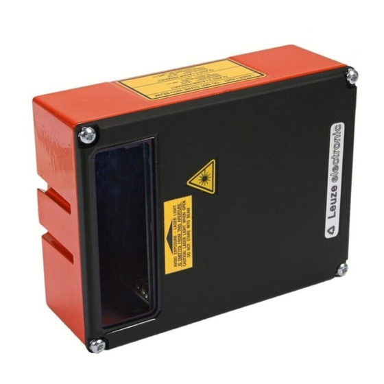
Leuze electronic Description Construction 3.3.1 BCL 40/device construction Dovetail fastening grooves Reading window 15-pin sub-D connector on the 4 fastening threads M4 on the underside of the rear of the device unit Figure 3.3: BCL 40/device construction BCL 40 Leuze electronic... -
Page 17: Device Construction Ma 10
Leuze electronic Description 3.3.2 Device construction MA 10 Mounting holes for the 4 Status-LEDs BCL 40 with M4 on the rear screws Cable screw glands PG11 for the power supply Cable screw glands PG11 for the power supply 15 pin Sub-D... -
Page 18: Specifications
Reading distance 0 … 700mm (depending on type of optics: N, M, F, L), see chapter 4.5.4 "Reading curves BCL 40 standard version" Reading field opening 70mm at a distance of approx. 10mm (see chapter 4.5.4 "Reading curves BCL 40 standard version") -
Page 19: Technical Data Bcl 40 With Heating
0.25mm … 1.0mm module width Reading distance 0 … 630mm (depending on type of optics: M, F, L) see chapter 4.5.5 "Reading curves BCL 40 with heating" Reading field opening Depending on the distance, the reading curve is typically approx. 20 … 70mm narrower see chapter 4.5.5 "Reading curves BCL 40 with heating"... -
Page 20: Technical Data Ma 10
Ambient temperature 0°C … +50°C/-20°C … +60°C (operation/storage) Air humidity max. 90% rel. humidity, non-condensing Vibration IEC 68.2.6 Shock IEC 68.2.27 IEC 801 Table 4.3: General Specifications MA 10 BCL 40 Leuze electronic Buy: www.ValinOnline.com | Phone 844-385-3099 | Email: CustomerService@valin.com... -
Page 21: Dimensioned Drawings
Leuze electronic Specifications Dimensioned drawings Rear view Plan view =110 M 4x6 (4x) Figure 4.1: Dimensioned drawing BCL 40 Plan view Rear view 22.5 M 4 (4x) Figure 4.2: Dimensioned drawing MA 10 Leuze electronic BCL 40 Buy: www.ValinOnline.com | Phone 844-385-3099 | Email: CustomerService@valin.com... -
Page 22: Optical Data
Specifications Optical Data The range at which the bar code can be read by the BCL 40 (the so-called reading field) depends not only on the quality of the printed bar code but also on its dimensions and the incident angle of the scanner beam. -
Page 23: Type Overview
Scanning Scanner type Part No. (mm) resolution rate (Sweep (mm) (scan/s) principle) BCL 40 R1 N 100 Raster 500 29678 20 …80 0.1 … 0.5 1200 BCL 40 S N 100 Single line 500 29679 BCL 40 R1 M 100... -
Page 24: Optics Variants
Sweep principle for the line scanner 4.5.3 Optics variants The BCL 40 is available with four different types of optics (N, M, F, L) that differ in range and resolution (see chapter 4.5.1 "Type overview"). Optic N: Zero to very short scanning ranges for very small modules. -
Page 25: Reading Curves Bcl 40 Standard Version
BCL 40 R1 M100 and BCL 40 S M100 Notice: All data in ’mm’, m = module width Figure 4.6: Reading curves BCL 40 standard version, optic variants N and M Leuze electronic BCL 40 Buy: www.ValinOnline.com | Phone 844-385-3099 | Email: CustomerService@valin.com... - Page 26 BCL 40 R1 L100 and BCL 40 S L100 Notice: All data in ’mm’, m = module width Figure 4.7: Reading curves BCL 40 standard version, optic variants F and L BCL 40 Leuze electronic Buy: www.ValinOnline.com | Phone 844-385-3099 | Email: CustomerService@valin.com...
-
Page 27: Reading Curves Bcl 40 With Heating
BCL 40 R1 L100 H and BCL 40 S L100 H Notice: All data in ’mm’, m = module width Figure 4.8: Reading curves BCL 40 with heating, optic variants M and L Leuze electronic BCL 40 Buy: www.ValinOnline.com | Phone 844-385-3099 | Email: CustomerService@valin.com... - Page 28 BCL 40 R1 F100 H and BCL 40 S F100 H Notice: All data in ’mm’, m = module width Figure 4.9: Reading curves BCL 40 with heating, optic variant F BCL 40 Leuze electronic Buy: www.ValinOnline.com | Phone 844-385-3099 | Email: CustomerService@valin.com...
-
Page 29: Accessories / Order Designation
Accessories / Order Designation Accessories Notice! Products from Leuze electronic GmbH & Co. can be ordered from any of the sales and serv- ice offices listed on the back page of this operating manual. 5.1.1 Bar code reader BCL 40 Symbol Order No. -
Page 30: Mounting Accessories
Accessories / Order Designation 5.1.3 Mounting accessories A wide range of mounting accessories are available for mounting the BCL 40 and MA 10. Mounting device BT 56 Clamping fixture for mounting to the BCL 40 or MA 10 Clamp for mounting to a round or oval pipe 16 …... -
Page 31: Cable Accessories
15-conductor connection cable BCL 40 / MA 10, Sub D plug and socket xxxx = length in mm Figure 5.3: Connection cable between the BCL 40 and MA 10 KB 040-xxxx-B 15-conductor connection cable, Sub D socket with open strand ends for connecting in switch-... -
Page 32: Installation
© Observe the local regulations regarding disposal and packaging. Cleaning © Clean the glass window of the BCL 40 with a soft cloth before mounting. Remove any remaining packaging from the device such as cardboard fibres and Styrofoam balls, par- ticularly in the area of the connector socket. -
Page 33: Mounting
6.2.1 Types of Mounting Accessories A wide range of mounting accessories are available for mounting the BCL 40 and MA 10: for more information see chapter 5 "Accessories / Order Designation". Mounting the BCL 40 There are two basic types of mounting arrangements for the BCL 40: •... - Page 34 Installation Mounting BCL 40 and MA 10 You can fasten the scanner BCL 40 and connector unit MA 10 tightly together to form a single compact unit. © Plug the two devices together at the 15 pin Sub D connector.
- Page 35 Mounting examples for the BCL 40 and MA 10 mounted independently You can mount the individual devices in the following way as already described above: • using the dovetail groove of the BCL 40 or the MA 10 and the corresponding mount- ing accessories •...
-
Page 36: Device Arrangement
Zero-distance scanner The BCL 40 M 100 is a "zero-distance" scanner, i.e. it already has a reading field width of 70 mm at a reading distance of 10 mm (module = 0.5). Labels are also read directly at the scanner window. - Page 37 Leuze electronic Installation BCL 40 BCL 40 to MA 10 10˚ 10˚ Width: 115 + cable outlet Width: 90 Figure 6.5: Minimum space requirements for installation Mounting location © When selecting a mounting location, pay attention to • maintaining the required environmental conditions (humidity, temperature), •...
- Page 38 MA 10 / opt. sensor Host interface Figure 6.6: Application example "conveyor chain" With its high scan rate of 1200 scans/s, the BCL 40 is particularly well suited for use with high-speed conveyor belts. BCL 40 Leuze electronic Buy: www.ValinOnline.com | Phone 844-385-3099 | Email: CustomerService@valin.com...
-
Page 39: Connection
Connection of the device and maintenance work while under voltage must only be carried out by a qualified electrician. The power supply unit used to power the BCL 40 and MA 10 must have protected electrical separation by way of a safety transformer with double insulation according to DIN VDE 0551 (IEC 742). -
Page 40: Connecting The Bcl 40 For "Stand Alone" Operation
Connecting the BCL 40 for "Stand Alone" Operation If you would like to connect the BCL 40 for "stand alone" operation, you must make a corre- sponding connector cable with a 15 pin Sub D plug (female) for the following connections: •... - Page 41 Leuze electronic Installation BCL 40 Sub D pin assignments 1 GND 9 Sensor 1B 2 Sensor 1A 10 NC 3 CTS (Host) 11 RXD (Host) 4 RTS (Host) 12 TXD (Host) 5 TXT Service 13 RXD Service 6 MODE-F 14 MODE-S...
-
Page 42: Leuze Electronic Bcl
0VDC Table 6.1: Wiring description BCL 40 6.3.2 Connecting the BCL 40 with the connector unit MA 10 Connection of the BCL 40 is considerably easier when using the MA 10. Sensor, Button Power supply Switching output host interface... -
Page 43: Figure 6.10: Disconnecting The Ribbon Cable Inside The Ma 10
All electrical connections can be carried out on the terminal strip quickly and without screw- ing down or soldering. Wires with ferruled ends can be inserted directly into the terminal without depressing the clamping lever. Leuze electronic BCL 40 Buy: www.ValinOnline.com | Phone 844-385-3099 | Email: CustomerService@valin.com... -
Page 44: Figure 6.11: Wiring To The Terminal Strip Without Screwing Down Or Soldering
The pin assignment of the connection terminals depends on the inserted interface module. Leuze offers four modules which can be used with the serial interfaces RS 485, RS 232, TTY or RS 422. The terminal designations are printed on the module. - Page 45 Terminals 1 through 6 are used depending on the type of interface: RS 232 RS 422 Terminal Signal Terminal Signal not used not used RS 485 Terminal Signal Terminal Signal 485A 485A 485B 485B not used Leuze electronic BCL 40 Buy: www.ValinOnline.com | Phone 844-385-3099 | Email: CustomerService@valin.com...
-
Page 46: Figure 6.13: Connecting The Ma 10 To A Rs 485 Host
Figure 6.14: Connecting the MA 10 to a RS 232 Host Notice for connecting the RS 232 interface: The wiring for RTS and CTS must only be connected, if RTS/CTS hardware-handshake is used. BCL 40 Leuze electronic Buy: www.ValinOnline.com | Phone 844-385-3099 | Email: CustomerService@valin.com... -
Page 47: Figure 6.15: Connecting The Ma 10 As Active Subscriber To A Tty Host
The active subscriber is the one which supplies the current (20mA). Switching between active/passive on the host interface card is carried out using two jumper pairs, independent for transmit (Tx) and for receive (Rx). Leuze electronic BCL 40 Buy: www.ValinOnline.com | Phone 844-385-3099 | Email: CustomerService@valin.com... -
Page 48: Figure 6.17: Connecting The Ma 10 To A Rs 422 Host
Each switching input is supplied with bi-directional optical couplers and protective resistors. The switching voltage and GND can be externally applied or taken from the operating voltage VDD_SE and GND_SE. BCL 40 Leuze electronic Buy: www.ValinOnline.com | Phone 844-385-3099 | Email: CustomerService@valin.com... -
Page 49: Figure 6.18: Connection Of The Switching Input With An External Switching Voltage
VDD_SE equal to V_IN device supply voltage, switching input, GND_SE equal to GND_IN device Supply voltage MA 10 / BCL 40: 18 … 36V MA 10 External Optically coupled switched input switching voltage to processor Figure 6.18: Connection of the switching input with an external switching voltage Supply voltage MA 10 / BCL 40: 18 …... -
Page 50: Figure 6.20: Position Of The Solder Jumpers Jl5 And Jl6
The solder jumpers are located on the circuit board of the MA 10 directly across from the connection terminals VDD_SA and GND_SA. Figure 6.20: Position of the solder jumpers JL5 and JL6 BCL 40 Leuze electronic Buy: www.ValinOnline.com | Phone 844-385-3099 | Email: CustomerService@valin.com... -
Page 51: Figure 6.21: Operating Voltage Used As The Switching Voltage
HI state (log.1). Please note that the event which sets the switching outputs must be set and activated in the software setup of the BCL 40. Leuze electronic BCL 40... -
Page 52: Wire Lengths And Shielding
Connection Interface Max. wire Shielding length BCL 40 - MA 10 RS 232 / RS 485 absolutely required, shield meshing BCL 40 - Host RS 232 / RS 485 absolutely required, shield meshing absolutely required, MA 10 - Host... -
Page 53: Commissioning
- Jumper below*: Data from BCL *In service operation, the jumper must be in the "lower" position. Communication is otherwise not possible. Figure 7.1: Control elements of the MA 10 Leuze electronic BCL 40 Buy: www.ValinOnline.com | Phone 844-385-3099 | Email: CustomerService@valin.com... - Page 54 • 0, if the combined BCL 40 / MA 10 unit will not be operated in a network, • 1 … 31, if several BCL 40 / MA 10 units will be operated in a network. Each multiNet plus network device must have a different device address assigned to it.
-
Page 55: Function Test
Notice! If the BCL 40 is to be operated as a "stand alone" device, a reset is only possible via soft- ware. There is a small green LED inside the BCL 40 at the lower edge of the reading window that displays the operation readiness. -
Page 56: Parameter Sets
The setting of the parameter sets then takes place in the operating mode "service", which is described in chapter 7.3.2. 7.3.1 Parameter sets Three different parameter sets are maintained by the MA 10 when using the BCL 40 / MA 10 combined unit: • the factory default parameter set • the customer-specific parameter set •... - Page 57 In this parameter set, the current settings for all device parameters are stored. If the BCL 40 is in "stand alone" operation, the parameter set is stored in the EEPROM of the BCL 40. If an MA 10 is also used, the parameter set is stored in EEPROM of the MA 10 and a copy thereof in the EEPROM of the BCL 40.
-
Page 58: Service Operating Mode
A PC or terminal can be connected to the MA 10 via the RS 232/V.24 serial interface and used to set the parameters of the BCL 40. The connection is made using a crossed RS 232 connection cable that establishes the RxD, TxD and GND connections. A hardware hand- shake via RTS, CTS is not supported at the service interface. -
Page 59: Setting Parameters "Offline
In setting 2 ("operation") of the operating mode switch, the terminal connector can be used as a data monitor. In this case, data sent from the BCL 40 (jumper in figure 7.1 in lower po- sition) or data received from host (jumper in figure 7.1 in upper position) can be logged. The data protocol is set by the host interface in the latter case. -
Page 60: Setting Parameters "Online
Number of labels to be decoded While "autoConfig" is active, have the BCL 40 read as many labels in row as it will later during a reading cycle when in normal operation. The number of labels can be set from "Set Code"... - Page 61 Code type and No. of characters of the label to be decoded The BCL 40 evaluates the number of labels, and at the same time, the code type and number of characters. This corresponds to the programming of the code types in the submenu "Decoding / Select Code Type"...
-
Page 62: Operation
"cold start" reset (> 4s) up until the reset button is released. All four LEDs blink • if the connection between the MA 10 and BCL 40 is interrupted. RDY blinks • during the "Power On" function test. -
Page 63: Important Functions During Operation
Operation Important Functions During Operation The BCL 40 has a function which automatically monitors the reading quality as well as the quality of the bar code label. "autoControl" function When the "autoControl" function is active, the BCL 40 constantly compares the total number of scans with the number of decoded scans. -
Page 64: Communicating With The Device
© Call up the installation file (e.g. Setup.exe) The following window appears: Installation window Figure 9.1: Installation window © Confirm the following licence agreement and select the installation path in the following window: BCL 40 Leuze electronic Buy: www.ValinOnline.com | Phone 844-385-3099 | Email: CustomerService@valin.com... -
Page 65: Graphic Configuration Using The "Bcl Configuration Tool" Software
Graphic configuration using the "BCL Configuration Tool" software In the following, you will find an overview and brief explanation of the adjustment options offered on the individual tabs. Leuze electronic BCL 40 Buy: www.ValinOnline.com | Phone 844-385-3099 | Email: CustomerService@valin.com... -
Page 66: Code Menu
Option Explanation Here, the codes which are to be decoded are set. As of software version V51.03 of BCL 40, the codes depicted above are enabled by default. We recommend enabling only the code types Code table which are to actually be read with the corresponding element numbers. -
Page 67: Figure 9.4: Properties Of The Decode Menu, Standard Setting
Specifies how often a code must be decoded before the result is valid Reading security and output. This value can be increased for inspection and test (equal scans) purposes. Leuze electronic BCL 40 Buy: www.ValinOnline.com | Phone 844-385-3099 | Email: CustomerService@valin.com... -
Page 68: Output Menu
This character is set for each unrecognised bar code. Multiple charac- No read string ters (= string) may be entered here. Up to 20 characters are possible. Set the desired formatting modes and formatting characters as Properties necessary. BCL 40 Leuze electronic Buy: www.ValinOnline.com | Phone 844-385-3099 | Email: CustomerService@valin.com... -
Page 69: Control
This item changes together with switching input 1 upon "Activation". Command The standard online character for the trigger end is the "-" character. characters This character can be changed only via the tree structure. Leuze electronic BCL 40 Buy: www.ValinOnline.com | Phone 844-385-3099 | Email: CustomerService@valin.com... -
Page 70: Communication
Communication -> Customer Interface -> 3964 / RK 512 Protocol. Attention! If the BCL 40 is operated in a network ("Leuze multiNet"), no changes may be made here. The scanner automatically sets itself to the multiNet protocol! BCL 40 Leuze electronic Buy: www.ValinOnline.com | Phone 844-385-3099 | Email: CustomerService@valin.com... -
Page 71: Figure 9.8: Properties Of The Communication Menu, Standard Setting
Properties of the Communication menu, standard setting Here, the frame format (prefix/postfix), the address mode as well as a BCC mode can be set. Attention! During Leuze multiNet operation, no changes may be made here! Leuze electronic BCL 40 Buy: www.ValinOnline.com | Phone 844-385-3099 | Email: CustomerService@valin.com... -
Page 72: Reference Code
Contents of the reference code Select here how the internally stored reference code is to be compared with the decoded result. Compare mode For additional comparison possibilities, please select the "Properties" menu. BCL 40 Leuze electronic Buy: www.ValinOnline.com | Phone 844-385-3099 | Email: CustomerService@valin.com... -
Page 73: Sensor
This parameter is used to extend the trigger signal internally by means Delay off time of software. Notice! If a BCL40 is operated without a MA10 or MA30 connector unit, only switching input 1 is available! Leuze electronic BCL 40 Buy: www.ValinOnline.com | Phone 844-385-3099 | Email: CustomerService@valin.com... -
Page 74: Switching Outputs
If the value here is set to 0, a continuous signal is applied to the switch- ing output which is not reset until the event on "deactivation". Notice! If a BCL 40 is operated without a MA10 or MA30 connector unit, no switching output is available! BCL 40 Leuze electronic Buy: www.ValinOnline.com | Phone 844-385-3099 | Email: CustomerService@valin.com... -
Page 75: Overview Of Commands And Parameters
Online commands can be used to send commands directly to the device for control and configuration. For this the BCL 40 / MA 10 must be connected to a host or service computer via the serial interface. The commands described can be sent either via the host or the service interface. -
Page 76: General "Online" Commands
General "Online" Commands Software version number Command ’V’ Description Requests device version information Parameter ’BCL 40’ ’V 50.09’ ’22.06.97’ Acknowledge- ’MA 10’ (only when a ’V 01.07’ MA 10 connector unit is installed) ment The device type appears in the first line followed by the software version number and date. - Page 77 ’10’ Add-on for EAN/UPC ’11’ Codabar No. of digits of the read code zzzzzz Contents of the decoded label. The ’, appears if the label was not correctly read. Leuze electronic BCL 40 Buy: www.ValinOnline.com | Phone 844-385-3099 | Email: CustomerService@valin.com...
- Page 78 Manual definition of the reference code Command ’RS’ This command can be used to define a new reference code in the BCL 40 by means of direct entry via the serial interface. The data are saved in the Description parameter set according to their input under reference code 1 or 2 and stored in the working buffer for further processing.
-
Page 79: Online" Commands For System Control
Deactivate sensor input 1 Command ’-’ Deactivates decoding (sensor input 1). A signal can be simulated on sen- Description sor input 1 with this command. Parameter Acknowledge- ment Leuze electronic BCL 40 Buy: www.ValinOnline.com | Phone 844-385-3099 | Email: CustomerService@valin.com... -
Page 80: Online" Commands For System Checking
’DS03’: invalid parameter for the command ’DL’ Acknowledge- ’DS04’: invalid command length ment ’DTxxx.x’ ’DCyyy’ xxx.x is the laser temperature in °C yyy is the laser current in mA BCL 40 Leuze electronic Buy: www.ValinOnline.com | Phone 844-385-3099 | Email: CustomerService@valin.com... - Page 81 Description minute. Supply voltage Command ’DUV’ Description Returns the supply voltage of the BCL 40. Parameter Acknowledge- ’DUVxx.x’ ment Description xx.x is the current supply voltage in V.
-
Page 82: Online" Commands For Querying Statistical Data
’ST17XXXXX’: XXXXX is the number of read enables since the last reset ’ST18XXXXX’: XXXXX the number of correctly decoded labels since the last reset ’ST19XXXXX’: XXXXX the number of incorrectly decoded labels since the last reset BCL 40 Leuze electronic Buy: www.ValinOnline.com | Phone 844-385-3099 | Email: CustomerService@valin.com... -
Page 83: Online" Commands For Parameter Set Operations
'3' invalid block check type ment '4' invalid block check checksum '5' invalid data length '6' invalid message data '7' invalid start address '8' invalid parameter set '9' invalid parameter type Leuze electronic BCL 40 Buy: www.ValinOnline.com | Phone 844-385-3099 | Email: CustomerService@valin.com... - Page 84 A valid parameter set operation must be acknowledged with ’PS0’. Should an error occur, the command should be repeated. Repeated error acknowledgements indicate an error in the parameter set. If in doubt, contact your Leuze sales or service office (see back page for addresses).
-
Page 85: Maintenance
Usually, the barcode reader BCL 40 does not require any maintenance by the operator. Cleaning Should it become soiled, clean the glass window of the BCL 40 with a soft cloth. Notice! Do not use aggressive cleaning agents such as thinner or acetone for cleaning the device. -
Page 86: Appendix
End of data trans. block CANCEL Invalid END OF MEDIUM End of message SUBSTITUTE Substitution ESCAPE Escape FILE SEPARATOR File separator GROUP SEPARATOR Group separator RECORD SEPARATOR Record separator BCL 40 Leuze electronic Buy: www.ValinOnline.com | Phone 844-385-3099 | Email: CustomerService@valin.com... - Page 87 COLON Colon SEMI-COLON Semicolon < LESS THEN Less than EQUALS Equal sign > GREATER THEN Greater than QUESTION MARK Question mark COMMERCIAL AT Commercial at character Capital letter Leuze electronic BCL 40 Buy: www.ValinOnline.com | Phone 844-385-3099 | Email: CustomerService@valin.com...
- Page 88 REVERSE SLANT Reverse slant CLOSING BRACKET Closing bracket CIRCUMFLEX Circumflex UNDERSCORE Underscore ‘ GRAVE ACCENT Grave accent Lower case letter Lower case letter Lower case letter Lower case letter BCL 40 Leuze electronic Buy: www.ValinOnline.com | Phone 844-385-3099 | Email: CustomerService@valin.com...
- Page 89 Lower case letter Lower case letter Lower case letter OPENING BRACE Opening brace VERTICAL LINE Vertical line CLOSING BRACE Closing brace TILDE Tilde DELETE (RUBOUT) Delete Table 11.1: ASCII Table Leuze electronic BCL 40 Buy: www.ValinOnline.com | Phone 844-385-3099 | Email: CustomerService@valin.com...
-
Page 90: Example Bar Code Label Types
Code type 10: EAN 13 Add-on SC 0 77889 abcde Code type 08: EAN 128 1 122334 455666 Modul 0,3 leuze Figure 11.1: Bar code sample labels (module width 0.3) BCL 40 Leuze electronic Buy: www.ValinOnline.com | Phone 844-385-3099 | Email: CustomerService@valin.com... -
Page 91: Module 0.5
Code type 10: EAN 13 Add-on SC 2 44332 fghij Code type 08: EAN 128 Modul 0,5 0 099887 766550 LEUZE Figure 11.2: Bar code sample labels (module 0.5) Leuze electronic BCL 40 Buy: www.ValinOnline.com | Phone 844-385-3099 | Email: CustomerService@valin.com...
Need help?
Do you have a question about the BCL 40 and is the answer not in the manual?
Questions and answers