Table of Contents
Advertisement
Advertisement
Table of Contents

Summary of Contents for SE Controls OS2
- Page 1 OS2 230v AC Controller Technical Information and Operating Instructions...
-
Page 2: Table Of Contents
OS2 230v AC Controller Installation and User Manual Table of Contents Section Reference Page Introduction Packaging & preparation Mounting Installation notes OS2 AC Controller Connections Pushbuttons Indicators Volt Free Status Connections Fuse Chart 10.0 Disposal 11.0 Health and Safety 12.0... -
Page 3: Introduction
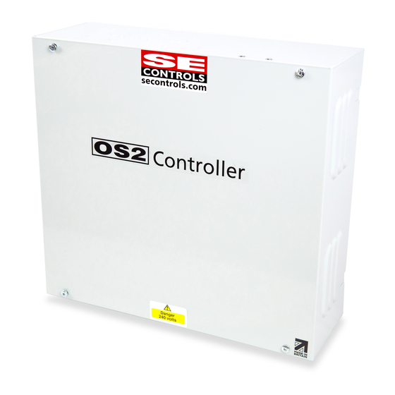
1.0 Introduction The OS2 AC Controller is a 230V AC control unit designed for use with 3-wire 230V AC actuators and magnets in a natural ventilation system. Brief device details: Power Class 1 Input supply 230V AC 50/60 Hz from a 6A fused un switched spur... -
Page 4: Packaging & Preparation
Use or connection of this controller for any other purpose than it is intended by the • manufacturer. SE Controls accepts no liability for failure to comply with the above statements or the installation and operation guidance in the following sections of this guide and reserves the right to invalidate the warranty of the controller. -
Page 5: Installation Notes
Please note that the controller enclosure is rated at IP20 and so should not be mounted: In damp or wet locations • Where there is likely to be significant amounts of dust. • • In areas classified as having a potentially explosive atmosphere. At this point it is recommended that the required number of cable entry glands is checked and any additional knock-outs required to achieve this are removed from the end of the controller. -
Page 6: Os2 Ac Controller Connections
5.0 OS2 AC Controller Connections 5.1 Introduction The following is a sketch which highlights the important features of the OS2 AC controller unit which are covered later in this document. All controller cable terminals have a capacity of 2.5mm stranded and 4mm solid core cables. - Page 7 5.2 Mains power connection Connect the 230V AC supply to the controller using a flexible cable (2 core + earth) of suitable cross section to the L, E and N terminals as shown. This cable should be capable of carrying the actuator load current up to a maximum of 6A @ 230V AC 5.3 Actuator Connections Two terminal blocks are supplied for the connection of actuators to the controller.
- Page 8 5.4 Control Connections Each controller can operate either as a stand alone unit or as part of a BMS managed control system. To allow for this level of control complexity, 7+1 control inputs are provided in the basic controller. The following list identifies the 7 controls in their priority order; Caretaker Demand Slave Demand &...
- Page 9 The slave inputs are designed to operate at 24VDC voltage levels. Connecting SBL and SBR to the 1BL and 1BR outputs of an OS2 type 21 controller (see typical arrangement below) will cause the local controller to act as a slave of the type 21 unit.
- Page 10 5.8 Rain Sensor Connecting RNS to 0V will close all attached actuators. By default, the thermostat, Day to Day and 0-10V inputs are all ignored under this condition. The lockout of the Day to Day input and 0-10V inputs can be modified at the factory by S E Controls.
- Page 11 In operation, power is applied to the actuator only during the period when one of the contacts is closed. This mode of operation is factory adjustable by S E Controls. In the open direction, the actuator power is automatically timed off when a total period of 18 seconds (factory adjustable) is exceeded.
- Page 12 By default, the 0-10V input is assumed to be an automatic control but can be adjusted at the factory by SE controls to be a manual control. 5.12 Auto/Manual input Connecting AUT to 0V will place the controller in automatic mode. Breaking the connection will place the...
- Page 13 In manual mode, all input controls will operate (thermostat, Day to Day and 0-10V). In automatic mode only automatic controls will operate (thermostat and 0-10V). Auto/manual changeover does not effect the operation of the Caretaker and Rain sensor inputs. To prevent confusion by a user of the Day to Day controls, each time this input is used, a timer with a 1 hour period (factory adjustable) is started.
-
Page 14: Pushbuttons
AC Supply 10A Note: If a fuse does blow, please check wiring/ external devices for damage and incorrect termination/earth faults. 10.0 Disposal For advice on disposal consult the local environmental officer, a recycling or waste management specialist or SE Controls. -
Page 15: Health And Safety
11.0 Health and Safety COSHH; There are no substances or products present or used in the manufacture of this controller that constitute a health risk 12.0 Contact Details Technical Support. SE Controls Lancaster House, Wellington Crescent, Fradley Park, Lichfield, Staffs. WS13 8RZ Tel 01543 443060 www.secontrols.com...


Need help?
Do you have a question about the OS2 and is the answer not in the manual?
Questions and answers