
Related Manuals for Daikin EKRCTRDI3BA


Summary of Contents for Daikin EKRCTRDI3BA
- Page 1 Installer and user reference guide Daikin Home Controls Room Thermostat - 2 EKRCTRDI3BA...
- Page 6 1.5 V LR03/micro/AAA batteries Installation and operation manual Documentation © 2022 Daikin Europe N.V., Belgium All rights reserved. This manual may not be reproduced in any format, either in whole or in part, nor may it be duplicated or edited by electronic, mechanical or chemical means, without the written consent of the publisher.
-
Page 7: Table Of Contents
Table of contents Information about this manual ........9 Hazard information ........... 9 Daikin Home Controls ..........11 Function and accessory overview ......12 Start-up..............14 Connecting DHC accessories ........14 5.1.1 Connecting to the DHC Access Point ....14 Mounting .............. - Page 8 Troubleshooting ............27 Weak battery ............... 27 Duty cycle ..............27 9.3 Error codes and flashing sequences ......29 10 Restore factory settings.......... 31 11 Maintenance and cleaning ........32 12 General information about radio operation ..... 33 13 Technical specifications .......... 34...
-
Page 9: Information About This Manual
Information about this manual Read this manual carefully before beginning operation with your Daikin Home Controls (DHC) accessories. Keep the manual so you can refer to it at a later date if you need to. If you hand over the accessory to other persons for use, hand over this manual as well. - Page 10 Hazard information The accessory may only be operated in a dry and dust-free environment and must be protected from the effects of moisture, vibrations, solar or other types of heat radiation, cold and mechanical loads. The accessory is not a toy; do not allow children to play with it.
-
Page 11: Daikin Home Controls
Daikin Home Controls Daikin Home Controls This accessory is part of the DHC ecosystem and commu- nicates with a dedicated wireless connection. All accessories of the system can be configured comfort- ably and individually via the ONECTA app. The available... -
Page 12: Function And Accessory Overview
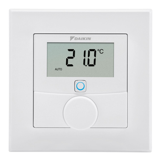
Function and accessory overview Function and accessory overview The DHC Room Thermostat enables time-controlled reg- ulation of your conventional radiators with DHC Radiator Thermostats, or of your floor heating in combination with DHC Floor Heating Controllers, and adjusts heating phases to your individual needs. - Page 13 Function and accessory overview Display overview (see figure 2): Setpoint/actual temperature Humidity Warning about condensation Open window symbol Battery symbol Radio transmission Boost function Manual mode* Automatic mode* Holiday mode* Heating Cooling Operating lock* Setpoint temperature * See „6 Configuration“ on page 20...
-
Page 14: Start-Up
To connect the DHC Room Thermostat to the DHC Access Point, proceed as follows: 1. Open the ONECTA app. 2. Click on the plus symbol (+). 3. Select the menu item Add Daikin Home Controls. 4. Select Add DHC Accessory. 5. Remove the electronic unit (B) from the frame:... - Page 15 Start-up grab the sides of the electronic unit and pull it from the mounting plate (see figure 6). 6. Turn over the electronic unit (B). 7. Remove the insulation strip from the battery com- partment. » Connection mode remains activated for 3 minutes. You can manually start the connection mode for another 3 minutes by pressing the system button (D) briefly (see figure 8).
-
Page 16: Mounting
Start-up Mounting Please read this entire section before st- arting to mount the accessory. You can use the supplied clip-on frame (A) to mount the DHC Room Thermostat or easily integrate it into an existing switch. If you want to mount the DHC Room Thermostat to a wall with the supplied clip-on frame, you can use •... -
Page 17: Screw Mounting
Start-up mounting plate (F) in the provided area. Make sure that you can read the letters on the back side (H) (see figure 3) and that the clips on the mounting plate latch into the openings on the DHC Room Thermostat. -
Page 18: Flush-Mounted Box Mounting
Start-up If you are working with a stone wall, drill the marked 5 mm holes and insert the plugs supplied. If you are working with a wooden wall, you can pre-drill 1.5 mm holes to easier insert the screws. 5. Use the supplied screws and plugs (K) to fix the mounting plate to the wall (see figure 5). - Page 19 Start-up Only to be installed by persons with the relevant electro-technical knowledge and experience!* Incorrect installation can put your own life at risk and the lives of other users of the electrical system. Incorrect instal- lation also means that you are running the risk of serious damage to property, e.g. because of a fire. You may be per- sonally liable in the event of injuries or damage to property.
-
Page 20: Configuration
Configuration quired additional measures etc.). Configuration The configuration of the accessory can be set up complete- ly in the ONECTA app. For further information on configura- tion of the accessory without using the DHC Access Point, see the DHC Application Guide. The following modes and settings can be adjusted: Automatic mode Manual mode Holiday mode Operating lock (not yet available) Programming a schedule Offset temperature (not yet available) Selecting a temperature display (not yet... -
Page 21: Automatic Mode
Holiday mode can be activated in the ONECTA app. It will put your system into standby. The holiday mode is visual- ized on your Daikin Altherma and on the Air Conditioning units in the ONECTA App. For further information, see the DHC Application Guide. -
Page 22: Programming A Schedule
DHC Application Guide. 6.5.1 Heating or cooling You can use your floor heating system to heat or cool rooms, provided your Daikin Altherma unit supports it. 6.5.2 Week schedule In the week schedule, you can set up to 6 time slots (13 change settings) for each weekday separately. -
Page 23: Selecting A Temperature Display (Not Yet Available)
Configuration the factory settings. This setting is not yet available in the ONECTA app and cannot be changed for the moment. Selecting a temperature display (not yet available) You can choose which temperature will be displayed on the accessory. There are 3 options: •... -
Page 24: Operation
Operation Operation After configuration, simple operations are available directly on the accessory. If the DHC Room Thermostat is in standby mode, press the control wheel (E) once before operation to activate it. Temperature: In automatic mode, manual chang- • es are activated until the next point at which the schedule changes. Afterwards, the defined heating schedule will be activated again. - Page 25 Replacing batteries pulled out of the frame (A) and removed from the mounting plate (F). Grab the sides of the electronic unit and pull it out (see figure 6). You do not need to open the accessory. 2. Turn the electronic unit over to remove or insert the batteries.
- Page 26 Replacing batteries heat. Do not short-circuit batteries. Doing so will present a risk of explosion. Used batteries should not be disposed of with reg- ular domestic waste! Instead, take them to your lo- cal battery disposal point.
-
Page 27: Troubleshooting
Troubleshooting Troubleshooting Weak battery Provided that the voltage value permits it, the accessory will remain ready for operation even if the battery voltage is low. Depending on the particular load, it may be possible to send transmissions again repeatedly, once the batteries have been allowed a brief recovery period. - Page 28 Troubleshooting the DHC accessory will stop transmitting until the time limit is reached. For example, when a device has a duty cycle limit of 1%, it is only allowed to transmit 36 seconds in 1 hour. After this, it will stop transmitting until the 1 hour limit is reached. DHC accessories fully comply to this limitation and use 2 frequency bands with a duty cycle of respectively 1 % and 10%.
-
Page 29: Error Codes And Flashing Sequences
Troubleshooting Error codes and flashing sequences Error and Meaning Solution flashing codes Battery Battery Replace the batter- symbol ( ) voltage too low ies of the accessory (see „8 Replacing batteries“ on page 24). Antenna Communication Check the con- symbol flashing problem with nection with the DHC Access DHC Access Point/... - Page 30 Troubleshooting Error and Meaning Solution flashing codes Short orange Radio transmis- Wait until the flashing sion/attempting transmission is to transmit/data completed. transmission 1x long green Operation Continue operation. lighting confirmed Short orange Connection Follow the instruc- flashing mode active tions in the app to (every 10 add accessory (see seconds)
-
Page 31: Restore Factory Settings
Restore factory settings Restore factory settings The factory settings of the accessory can be re- stored. If you do this, you will lose all your settings. To restore the factory settings of the accessory, proceed as follows: 1. Grab the sides of the electronic unit (B) and pull it out of the frame (see figure 6). -
Page 32: Maintenance And Cleaning
Maintenance and cleaning Maintenance and cleaning The accessory does not require you to carry out any maintenance other than replacing the battery when necessary. Enlist the help of an expert to car- ry out any maintenance or repairs. Clean the accessory using a soft, lint-free cloth that is clean and dry. -
Page 33: General Information About Radio Operation
Hereby, Daikin Europe N.V. declares that the radio equip- ment type DHC EKRCTRDI3BA is in compliance with the Directive 2014/53/EU. The original declaration of confor- mity is available from the EKRCTRDI3BA product pages. -
Page 34: Technical Specifications
Technical specifications Technical specifications Device name: EKRCTRDI3BA Supply voltage: 2x 1.5 V LR03/micro/AAA Current consumption: 50 mA max. Battery life (typ.): 2 years Degree of protection: IP20 Ambient temperature: 0 to 35 °C Dimensions (W x H x D): Without frame: 55 x 55 x 23.5 mm... - Page 35 Technical specifications Instructions for disposal Do not dispose of the device with regular domestic waste! Electronic equipment must be disposed of at local collection points for waste electronic equip- ment in compliance with the Waste Electrical and Electronic Equipment Directive. Information about conformity The CE sign is a free trading sign addressed exclu- sively to the authorities and does not include any warranty of any properties.
- Page 36 Free download of the ONECTA app! 4P687366-1 - 2022.04...
Need help?
Do you have a question about the EKRCTRDI3BA and is the answer not in the manual?
Questions and answers