Table of Contents
Advertisement
Quick Links
Advertisement
Table of Contents

Subscribe to Our Youtube Channel
Summary of Contents for Kramer MegaTOOLS TP-575
-
Page 1: User Manual
Kramer Electronics, Ltd. USER MANUAL Model: TP-575 HDMI Line Receiver / DA... -
Page 2: Table Of Contents
Acquiring the EDID Technical Specifications Figures Figure 1: TP-575 HDMI Line Receiver / DA Figure 2: Connecting a TP-575 HDMI Line Receiver / DA Figure 3: CAT 5 PINOUT Tables Table 1: TP-575 HDMI Line Receiver / DA Features Table 2: CAT 5 PINOUT... -
Page 3: Introduction
GROUP 7: Scan Converters and Scalers; GROUP 8: Cables and Connectors; GROUP 9: Room Connectivity; GROUP 10: Accessories and Rack Adapters; GROUP 11: Sierra Products 2 Download up-to-date Kramer user manuals from the Internet at this URL: http://www.kramerelectronics.com 3 The complete list of Kramer cables is on our Web site at http://www.kramerelectronics.com... -
Page 4: Quick Start
Getting Started Quick Start This quick start chart summarizes the basic setup and operation steps. KRAMER: SIMPLE CREATIVE TECHNOLOGY... -
Page 5: Overview
Overview Overview The TP-575 is a twisted pair line driver and DA for HDMI. The TP-575 receives an HDMI signal from a transmitter (for example, the Kramer PT-571) via the LINE IN RJ-45 connector. It decodes this input signal to the local output... -
Page 6: About Hdmi
Overview The TP-575 is 12V DC fed and is housed in a MegaTOOLS® enclosure where two units can be rack mounted side-by-side in a 1U rack space with the optional RK-T2B rack adapter. About HDMI High-Definition Multimedia Interface (HDMI) is an uncompressed all-digital audio/video interface, widely supported in the entertainment and home cinema industry. -
Page 7: Defining Edid
The Power Connect™ feature here means that the TP-575 unit can power both the transmitter and receiver when they are within 270 feet (90 meters) of the TP-575. The Power Connect™ feature applies as long as the cable can carry power. The distance does not exceed 90 meters on standard twisted... -
Page 8: Your Tp-575 Hdmi Line Receiver / Da
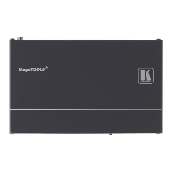
Figure 1 Table 1 define the TP-575 HDMI Line Receiver / DA: Figure 1: TP-575 HDMI Line Receiver / DA Table 1: TP-575 HDMI Line Receiver / DA Features Feature Function EDID SETUP Button Press briefly to determine the type of EDID stored in the non-... -
Page 9: Using The Tp-575 Hdmi Line Receiver / Da
3. On the TP-575, connect the OUT 2 (HDMI) connector to an HDMI acceptor (for example, a plasma display). 4. Connect the OUT 1 (LINE) CAT 5 RJ-45 connector on the TP-575 to the CAT 5 IN RJ-45 connector on the PT-572+ via a twisted pair cable (see section 5.2). -
Page 10: Figure 2: Connecting A Tp-575 Hdmi Line Receiver / Da
Using the TP-575 HDMI Line Receiver / DA Figure 2: Connecting a TP-575 HDMI Line Receiver / DA KRAMER: SIMPLE CREATIVE TECHNOLOGY... -
Page 11: Wiring The Twisted Pair Line In / Line Out Rj-45 Connectors
Using the TP-575 HDMI Line Receiver / DA Wiring the Twisted Pair LINE IN / LINE OUT RJ-45 Connectors Table 2 Figure 3 define the STP CAT 5 PINOUT , using a straight pin-to-pin cable with RJ-45 connectors (note, that the cable Ground... -
Page 12: Acquiring The Edid
The EDID is now acquired. 1 The TP-575 reads the EDID, which is stored in the non-volatile memory 2 This is usually done only once, when the machine is being set up in an installation. Once acquired, the EDID is saved in... -
Page 13: Technical Specifications
Technical Specifications Technical Specifications of the TP-575: Table 3 includes the technical specifications Table 3: Technical Specifications of the TP-575 INPUT: 1 TP on an RJ-45 connector OUTPUTS: 1 TP on an RJ-45 connector 1 HDMI connector BANDWIDTH: Supports up to 1.65Gbps bandwidth per graphic channel... - Page 14 EXCLUSION OF DAMAGES The liability of Kramer for any effective products is limited to the repair or replacement of the product at our option. Kramer shall not be liable for: 1. Damage to other property caused by defects in this product, damages based upon inconvenience, loss of use of the product, loss of time, commercial loss;...
- Page 15 For the latest information on our products and a list of Kramer distributors, visit our Web site: www.kramerelectronics.com, where updates to this user manual may be found. We welcome your questions, comments and feedback. Safety Warning: Disconnect the unit from the power supply before opening/servicing.


Need help?
Do you have a question about the MegaTOOLS TP-575 and is the answer not in the manual?
Questions and answers