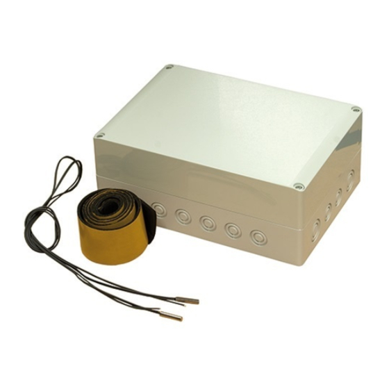
Nibe AXC 40 Installer Manual
Hide thumbs
Also See for AXC 40:
- Installer manual (72 pages) ,
- Installer manual (60 pages) ,
- Installer manual (64 pages)
Table of Contents
Advertisement
Quick Links
Advertisement
Table of Contents

Summary of Contents for Nibe AXC 40
- Page 1 Installer manual AXC 40 Accessories IHB GB 0935-1 031444...
-
Page 3: Table Of Contents
Electrical circuit diagram 3 Mixing valve controlled additional heat (oil/gas boiler/district heat- 5 Groundwater pump ing) General General Outline diagram Pipe connections Electrical connection Outline diagram Program settings Electrical connection Electrical circuit diagram Program settings AXC 40 Table of Contents |... -
Page 4: General
Miniature circuit-breaker Terminal block, power supply Accessory card AA5-X2 Terminal block, sensors and external blocking AA5-X4 Terminal block, communication AA5-X9 Terminal block, circulation pump, mixing valve and auxiliary relay AA5-S2 DIP switch AA5-F1 Fine-wire fuse Chapter 1 | General AXC 40... -
Page 5: Common Electrical Connection
Use cable type LiYY, EKKX or similar. F1145/F1245 must not be powered when in- F1145/F1245 stalling AXC 40. AA3-X4 AA3-X4 Electrical circuit diagrams are at the end of the chapter for each connection option. -
Page 6: Mixing Valve Controlled Additional Heat 4 X
The heat pump controls a mixing valve and a circulation in the external addition. pump via AXC 40. If the heat pump does not manage to External flow temperature sensor (BT25) must be in- keep the correct flow temperature, the addition starts stalled on the flow line to the radiators, after the and the mixing valve (QN11) opens from the addition. -
Page 7: Outline Diagram
QM32 QN11 Mixing valve, addition HQ1, HQ4 Particle filter Accessory card, addition Non-return valve Auxiliary relay, addition GP10 Circulation pump, climate system Outline diagram F1145 with AXC 40 and external addition -FL2 -CM4 -BT52 -EM1 -BT25 -GP10 -QN11 -RM1 -EM1-KA1... - Page 8 Outline diagram F1245 with AXC 40 and external addition -FL2 -CM4 -BT52 -EM1 -BT25 -GP10 -QN11 -RM1 -EM1-KA1 -EM1-AA5 -BT1 -FL2 -CM1 -QM31 -HQ1 -QM32 -EB100 F1245 Chapter 3 | Mixing valve controlled additional heat (oil/gas boiler/district heating) AXC 40...
-
Page 9: Electrical Connection
Electrical installation and wiring must be carried out in accordance with the stipulations in force. BT25 BT25 F1145/F1245 must not be powered when in- stalling AXC 40. AA3-X6 AA3-X6 Connection of sensors and external blocking F1245 Use cable type LiYY, EKKX or similar. -
Page 10: Program Settings
Connection of the mixing valve motor (QN11) Program settings Connect the mixing valve motor (QN11) to AA5-X9:6 Program setting of AXC 40 can be performed via the start (230 V, open), AA5-X9:5 (N) and AA5-X9:4 (230 V, close). guide or directly in the menu system. -
Page 11: Electrical Circuit Diagram
Electrical circuit diagram AXC 40 Chapter 3 | Mixing valve controlled additional heat (oil/gas boiler/district heating) -
Page 12: Hot Water Circulation
Accessory card, hot water circulation QM31, Shut-off valve QM32 4-way valve, hot water circulation Particle filter QN3, QN4 Control valve RM3, RM4 Non-return valve Outline diagram F1145 with AXC 40 and hot water circulation -BT1 -FL2 -CM1 -GP11-AA5 -GP11 -QM31 -QN4 -RM4 -QN3... - Page 13 Outline diagram F1245 with AXC 40 and hot water circulation -BT1 -FL2 -GP11-AA5 -CM1 -QM31 -GP11 -HQ1 -QM32 -QN4 -RM4 -QN3 -QN2 -RM3 -EB100 -EB2 F1245 AXC 40 Chapter 4 | Hot water circulation...
-
Page 14: Electrical Connection
Electrical connection Program settings Program setting of AXC 40 can be performed via the start NOTE guide or directly in the menu system. All electrical connections must be carried out by Start guide an authorised electrician. The start guide appears upon first start-up after heat Electrical installation and wiring must be carried pump installation, but is also found in menu 5.7. -
Page 15: Electrical Circuit Diagram
Electrical circuit diagram AXC 40 Chapter 4 | Hot water circulation... -
Page 16: Groundwater Pump
QM34, Shut-off valve QM42 Accessory card, ground water QM12 Filler valve Heat exchanger, ground water Level vessel Particle filter Safety valve Outline diagram F1145 with AXC 40 and ground water pump -BT1 -QM12 -CM2 -QM42 -XL15 -FL3 -QM34 -EB100 -EP12-AA5... - Page 17 Outline diagram F1245 with AXC 40 and ground water pump -BT1 -QM12 -CM2 -QM42 -XL15 -FL3 -QM34 -EB100 -EP12-AA5 -HQ2 -EP4 -EP12 -GP3 F1245 AXC 40 Chapter 5 | Groundwater pump...
-
Page 18: Electrical Connection
Electrical connection Program settings Program setting of AXC 40 can be performed via the start NOTE guide or directly in the menu system. All electrical connections must be carried out by Start guide an authorised electrician. The start guide appears upon first start-up after heat Electrical installation and wiring must be carried pump installation, but is also found in menu 5.7. -
Page 19: Electrical Circuit Diagram
Electrical circuit diagram AXC 40 Chapter 5 | Groundwater pump... - Page 20 Chapter 5 | AXC 40...
- Page 21 AXC 40 Chapter 5 |...
- Page 22 Chapter 5 | AXC 40...
- Page 24 NIBE AB Sweden Järnvägsgatan 40 Box 14 SE-285 21 Markaryd info@nibe.se www.nibe.eu...


Need help?
Do you have a question about the AXC 40 and is the answer not in the manual?
Questions and answers