Table of Contents
Advertisement
Quick Links
ise smart connect Modbus Vaillant
Product Manual
Product Manual
ise smart connect Modbus Vaillant
Order no. S-0002-007
Complete set for installation, consisting of the two system components:
- ise smart connect Modbus Vaillant and
- ise eBUS Adapter
Order no. 1-0009-000
- ise smart connect Modbus Vaillant
Order no. 2-0001-003
- ise eBUS Adapter
Valid for firmware version 1.0
Advertisement
Table of Contents

Related Manuals for ISE smart connect Modbus Vaillant


Summary of Contents for ISE smart connect Modbus Vaillant
- Page 1 Product Manual ise smart connect Modbus Vaillant Order no. S-0002-007 Complete set for installation, consisting of the two system components: - ise smart connect Modbus Vaillant and - ise eBUS Adapter Order no. 1-0009-000 - ise smart connect Modbus Vaillant Order no.
-
Page 2: Table Of Contents
Connection of the ise eBUS Adapter with the eBUS ............... 11 Configuration ........................12 Configuration step 1 – IP configuration of the ise smart connect Modbus Vaillant ....13 Configuration step 2 – Configuration of system dimensioning ..........14 Configuration step 3 – Configuration of the Modbus TCP/IP port..........15 Modbus TCP/IP ........................ - Page 3 License agreement ise smart connect Modbus Vaillant software ........35 Definitions ..........................35 Object of the agreement ......................35 Rights of use of the ise smart connect Modbus Vaillant software ........... 35 Restriction of rights of use ...................... 35 9.4.1 Copying, modification and transmission ................35 9.4.2 Reverse engineering and conversion technologies ............
- Page 4 Modbus Vaillant Product Manual GNU GENERAL PUBLIC LICENSE ..................41 Order No. S-0002-007 Product Manual Page 4 (45)
-
Page 5: Product Description
The ise eBUS Adapter is a system component to connect the Vaillant bus modular control with the Modbus system. It connects: - devices of the ise smart connect series for eBUS connection (in this case, ise smart connect Modbus Vaillant) and - the Vaillant system together over a USB interface. -
Page 6: Function Schematic
Modbus Vaillant Product description Function schematic Building Management System (BMS) eBUS geoTHERM/3 Accessory VWS220/3 – 460/3 Modbus TCP/IP Order No. S-0002-007 Product Manual Page 6 (45) -
Page 7: Installation, Electrical Connection And Operation
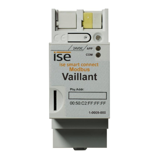
Modbus Vaillant Installation, electrical connection and operation Installation, electrical connection and operation Device design ise smart connect Modbus Vaillant 24 V DC Dimensions: Width (W): 36 mm (2 HP) Height (H): 24VDC 90 mm ise smart connect... -
Page 8: Safety Notes
Connect the network connection to the RJ pin jack with the RJ45 plug (6) to enable Modbus TCP/IP access. Connect the ise eBUS adapter to the USB port (7) (use the supplied USB cable). Please note that the use of USB cables with a length of more than 3 m is generally not permitted. When con- necting an active ise smart connect Modbus Vaillant with the ise eBUS Adapter, the initialisation may require up to three minutes. - Page 9 Modbus Vaillant Installation, electrical connection and operation Mounting/removing a cover cap A cover cap can be mounted for protection of the power supply connections from dangerous voltage, particularly in the connection area. The cap is mounted with an attached power supply terminal and a connected power supply line to the rear.
-
Page 10: Device Design Ise Ebus Adapter
Figure 3: ise eBUS Adapter Important note: The maximum length of the eBUS connection cable is 125 m. Please see chapter 2.5 “Connection of the ise eBUS eBUS connection Adapter with the eBUS” for the position of the eBUS connection. The connection is protected against polarity reversal. -
Page 11: Connection Of The Ise Ebus Adapter With The Ebus
Adapter. Figure 4: Junction box for the connection of the ise eBUS Adapter to the heating system. The position of the junction box can be seen in the “Handover protocol from executing company for heating, air conditioning, ventilation technology to the building technology planner”. -
Page 12: Configuration
Modbus Vaillant Configuration Configuration Configuration of the ise smart connect Modbus Vaillant system components is divided into the following steps: For explana- Preparations: tions, see Installing ise eBUS Adapter. Connect the ise smart connect Modbus Vaillant with the ise eBUS Adapter via the USB interface. -
Page 13: Configuration Step 1 - Ip Configuration Of The Ise Smart Connect Modbus Vaillant
By default, the ise smart connect Modbus Vaillant requests its IP configuration via DHCP. If the default setting is used, a DHCP server will assign a valid IP address to the ise smart connect Modbus Vaillant. If a DHCP server is not available for this setting, the device starts up after a short time with an AutoIP address (address range from 169.254.1.0 to 169.254.254.255). -
Page 14: Configuration Step 2 - Configuration Of System Dimensioning
Modbus Vaillant Configuration Configuration step 2 – Configuration of system dimensioning The heating system dimensioning can easily be configured via the device website. In addition to the Vaillant geoTHERM/3 heat pump, you can also control up to three Vaillant VR60 mixer modules and up to six Vaillant VR90 remote control units. -
Page 15: Configuration Step 3 - Configuration Of The Modbus Tcp/Ip Port
Modbus Vaillant Configuration Configuration step 3 – Configuration of the Modbus TCP/IP port If needed, you can change the Modbus TCP/IP port of the device on the website. You can find this op- tion on the Vaillant components subpage. By default, the port is 502. It is possible to configure a port in the range between 2,000 and 4,000. -
Page 16: Modbus Tcp/Ip
Modbus Vaillant Modbus TCP/IP Modbus TCP/IP Modbus function codes The following function codes are supported via Modbus TCP/IP: Function Name code 0x03 Read Holding Registers 0x04 Read Input Registers 0x06 Write Single Register 0x10 Write Multiple Registers... -
Page 17: Modbus Tcp/Ip Unit Ids
Modbus Vaillant Modbus TCP/IP Modbus TCP/IP unit IDs The Modbus TCP/IP gateway manages the following unit IDs: Unit ID Description Vaillant geoTHERM/3 Vaillant geoTHERM/3 domestic hot water Vaillant geoTHERM/3 auxiliary heater Vaillant VR60 heating circuit 4 Vaillant VR60 heating circuit 5... - Page 18 Modbus Vaillant Modbus TCP/IP Addr. Name Datatype Polling Range Reso- Unit interval lution [min] Pressure compressor low sensorState sensor state 0 – 65.5 22-23 Pressure compressor low IEEE 754 single float 2 sensor value Compressor outlet sensorState temperature sensor state -2048 –...
-
Page 19: Holding Registers (R/W)
Modbus Vaillant Modbus TCP/IP Addr. Name Datatype Polling Range Reso- Unit interval lution [min] Mixer activation mixerDutyState Heating circuit status pump status 4.5.1.2 Holding Registers (R/W) Addr. Name Datatype Polling Range Reso- Unit interval lution [min] 7 – 100... -
Page 20: Unit Id 3: Vaillant Geotherm/3 Auxiliary Heater
Modbus Vaillant Modbus TCP/IP 4.5.3 Unit ID 3: Vaillant geoTHERM/3 auxiliary heater 4.5.3.1 Input Registers (R) Addr. Name Datatype Polling Range Reso- Unit interval lution [min] Backup commutations uint32_t Backup heater operating uint32_t hours Backup heater output status 4.5.3.2... -
Page 21: Holding Registers (R/W)
Value Description No Error geoTHERM/3, VR60 or VR90 not found No compatible geoTHERM/3, VR60 or VR90 found Error in communication with the ise eBUS Adapter eBUS cable not connected No answer from eBUS Value not permitted Order No. S-0002-007... -
Page 22: Sensorstate
Modbus Vaillant Modbus TCP/IP 4.6.3 sensorState Value Description No fault Short-circuit Interrupt 4.6.4 status Value Description 4.6.5 DTC_EHP The “error number geoTHERM/3” is the error number displayed on the geoTHERM/3 controller. Value Error number Description geoTHERM/3 Error comp inlet sensor... - Page 23 Modbus Vaillant Modbus TCP/IP Value Error number Description geoTHERM/3 Op Interlock: Heat source anti freezing protection : T5<4°C Op Interlock: Heat source anti freezing protection : T6<-10°C Op Interlock: No water flow Op Interlock: C-H circuit anti freezing protection...
-
Page 24: Statusmessageehp
Modbus Vaillant Modbus TCP/IP 4.6.6 statusMessageEHP Value Description Standby Cooling De-icing CH: Comp. only CH: Comp & Aux CH: Aux only CH: Comp & aux off DHW: Comp & aux off DHW: Comp only DHW: Aux only... -
Page 25: Opmodedhw
Modbus Vaillant Modbus TCP/IP 4.6.9 opModeDHW Value Description Auto 4.6.10 opModeHC Value Description Auto Order No. S-0002-007 Product Manual Page 25 (45) -
Page 26: Commissioning
Modbus Vaillant 00:00:00:00:00:00 1-0009-000 Figure 5: ise smart connect Modbus Vaillant. Button for factory reset The button can be used to execute a factory reset of the device. DC 24–30 V, 2 W (at 24 V) Connection for... -
Page 27: Led Status Displays
Modbus Vaillant Commissioning LED status displays The device features three status LEDs on the upper housing side and two status LEDs on the network connections. The LED displays have different meanings while the device is starting and ... -
Page 28: Led Status Display In Operation
Error in communication with the ise eBUS Adapter. Communication be- Three slow flashes fol- tween the ise smart connect Modbus Vaillant and the ise eBUS Adapter is lowed by a 2 s pause not possible via USB or eBUS cable is not connected, eBUS connection not recognised. -
Page 29: Accessing The Website Of The Device
Modbus Vaillant Commissioning Accessing the website of the device To access the website of the device, you can use one of the following steps: Double-click the icon of the device in the Other Devices area in the network environment. -
Page 30: Firmware Update
Firmware Update using the Website of the Device The ise smart connect Modbus Vaillant provides a way to install a firmware update via the device web- site. To do this, please choose Firmware update from the menu on the device website. The ise smart connect Modbus Vaillant will automatically check for a new version with our update server. -
Page 31: Technical Data
DC 24 to 30 V ±10% Connection Bus connection terminal, preferably yellow (+)/white (–) typ. 1.2 W (with DC 24 V and connected ise eBUS Adapter) Power consumption The device must be supplied with voltage by a dedicated power supply unit. Do not use the auxiliary voltage output of a KNX power supply unit which is also supplying a KNX line. -
Page 32: Frequently Asked Questions (Faq)
Frequently asked questions (FAQ) How do I find out the IP address of my ise smart connect Modbus Vaillant? Please read about this in chapter 8.2 “Device status page of the ise smart connect Modbus Vail- lant”. Are there software updates for my ise smart connect Modbus Vaillant device? Please read about this in chapter 5.5 “Firmware Update”. -
Page 33: Troubleshooting And Support
Device status page of the ise smart connect Modbus Vaillant You can call up the device status on the website of the ise smart connect Modbus Vaillant (see chapter 5.3 “Accessing the website of the device”). It is divided into three sections. -
Page 34: The Ise Smart Connect Modbus Vaillant Does Not Work
Modbus Vaillant Troubleshooting and support The ise smart connect Modbus Vaillant does not work The following error tree is intended to solve the most common problems. Should this be unsuccessful, please contact us at support@ise.de. Please check the cabling Are the LEDs not light- according to chapter 2.5... -
Page 35: License Agreement Ise Smart Connect Modbus Vaillant Software
Modbus Vaillant. ise smart connect Modbus Vaillant software: The ise smart connect Modbus Vaillant software desig- nates all of the software provided for the ise smart connect Modbus Vaillant product, including the oper- ating data. This includes, in particular, the firmware. -
Page 36: Transfer To A Third Party
License agreement ise smart connect Modbus Vaillant software 9.4.4 Transfer to a third party The ise smart connect Modbus Vaillant software may not be passed on to third parties, nor may it be made accessible to third parties. 9.4.5 Renting out, leasing out and sub-licensing The Licensee is not authorised to rent or lease the ise smart connect Modbus Vaillant software or grant sub-licenses to the program. -
Page 37: Software And Documentation
The Licensor shall not be liable for damages due to loss of profit, data loss or any other financial loss resulting as part of the use of the ise smart connect Modbus Vaillant software, even if the Licensor is aware of the possibility of damage of that type. -
Page 38: Subsidiary Agreements And Changes To The Agreement
Modbus Vaillant License agreement ise smart connect Modbus Vaillant software 9.11 Subsidiary agreements and changes to the agreement Subsidiary agreements and changes to the agreement shall only be valid in writing. 9.12 Exception All rights not expressly mentioned in this agreement are reserved. -
Page 39: Open Source Software
Modbus Vaillant Open Source Software Open Source Software This product uses software from third-party sources used within the scope of the GNU General Public License (GPL) or Lesser GNU General Public License LGPL and within the scope of the Berkeley Soft- ware Distribution (BSD) and the MIT license. - Page 40 Modbus Vaillant Open Source Software Software package jQuery Version of the software 1.11.1 Source https://jquery.org License MIT Licence Copyright notice Copyright 2014 The jQuery Foundation Software package libzip Version of the software 1.1.2 Source https://nih.at/libzip License https://nih.at/libzip/LICENSE.html...
- Page 41 Modbus Vaillant GNU GENERAL PUBLIC LICENSE GNU GENERAL PUBLIC LICENSE Version 2, June 1991 Copyright (C) 1989, 1991 Free Software Foundation, Inc. 51 Franklin Street, Fifth Floor, Boston, MA 02110-1301, USA Everyone is permitted to copy and distribute verbatim copies of this license document, but changing it is not allowed.
- Page 42 Modbus Vaillant GNU GENERAL PUBLIC LICENSE The precise terms and conditions for copying, distribution and modification follow. TERMS AND CONDITIONS FOR COPYING, DISTRIBUTION AND MODIFICATION 0. This License applies to any program or other work which contains a notice placed by the copyright holder saying it may be distributed under the terms of this General Public License.
- Page 43 Modbus Vaillant GNU GENERAL PUBLIC LICENSE These requirements apply to the modified work as a whole. If identifiable sections of that work are not derived from the Program, and can be reasona- bly considered independent and separate works in themselves, then this Li- cense, and its terms, do not apply to those sections when you distribute them as separate works.
- Page 44 Modbus Vaillant GNU GENERAL PUBLIC LICENSE 4. You may not copy, modify, sublicense, or distribute the Program except as expressly provided under this License. Any attempt otherwise to copy, mod- ify, sublicense or distribute the Program is void, and will automatically terminate your rights under this License.
- Page 45 Modbus Vaillant GNU GENERAL PUBLIC LICENSE geographical distribution limitation excluding those countries, so that dis- tribution is permitted only in or among countries not thus excluded. In such case, this License incorporates the limitation as if written in the body of this License.
Need help?
Do you have a question about the smart connect Modbus Vaillant and is the answer not in the manual?
Questions and answers