Advertisement
Quick Links
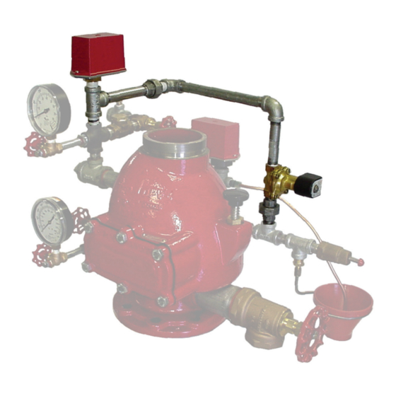
Model QRS Electronic Accelerator
(Quick Opening Device)
For Dry Pipe or Preaction Systems
General
Description
The TYCO Model QRS Electronic
Accelerator is a quick opening device
intended to reduce the operating time
of a dry pipe valve in a dry pipe system
or an automatic control valve (deluge
valve) in a double interlock electric/
electric preaction system.
The control panel for the QRS may be
used with up to four QRS switches for
one to four system risers using one of
the following dry pipe valves:
• TYCO 4 in. & 6 in. (DN100/150)
Model DPV-1 Dry Pipe Valves
• Central 3 in. (DN80) Model AF or
Central 4 in. & 6 in. (DN100/150)
Model AF/AG Dry Pipe Valves
• Gem 4 in. & 6 in. (DN100/150) Model
F302/F3021 Dry Pipe Valves
• Star 4 in. & 6 in. (DN100/150) Models
A or A-1 Dry Pipe Valves
The control panel for the QRS may
be used with one QRS switch for one
system riser using the following auto-
matic control valve (deluge valve) used
in a double interlock electric/electric
preaction system:
• TYCO 1-1/2 in. through 8 in. (DN40
through DN200) DV-5
Deluge Valve
A
The Model QRS Electronic Accelerator
(see Figure 1) utilizes a unique system
air pressure monitoring device (UL and
C-UL Listed, as well as FM Approved,
Model QRS Extinguishing System
Attachment) that continuously samples
air pressure twice per sec ond. When
the air pressure is deter mined to have
a sustained drop ex ceeding a rate of
0.1 psi (0,007 bar) per second as veri-
fied by three con secutive samplings,
the QRS signals the Releasing Panel
(Model PFC 4410-RC) via its "Panel
Input" initiating zone circuit, which
energizes the Sole noid Valve.
IMPORTANT
Refer to Technical Data Sheet
TFP2300 for warnings pertaining to
regulatory and health information.
Page 1 of 16
In the case of a dry pipe valve, the
energized Solenoid Valve introduces
system air pressure to the interme-
diate chamber of the dry pipe valve.
This pressure neutralizes the differen-
tial pressure holding the dry pipe valve
closed and permits it to open.
In the case of a double interlock elec-
tric/electric preaction system, the
energized Solenoid Valve releases dia-
phragm pressure from the automatic
control valve (deluge valve) to permit
the automatic control valve (deluge
valve) to open.
The Model QRS Electronic Accelera-
tor automatically adjusts to both small
and slow changes in system pressure,
but trips when there is a steady drop
in pressure (as in the case of sprinkler
operation).
The QRS Electronic Accelerator fea-
tures the following:
• Operation of a dry pipe or preaction
valve within four seconds — inde-
pendent of various combinations of
system initial air pressures, system
volumes, or sprinkler K-factors
• One Releasing Panel can control
up to four dry pipe systems or one
double interlock preaction system
• Built-in low pressure and high
pressure alarm supervision
• Proven electric release technology
as used for electrically operated
del uge and preaction systems
• Battery back-up in the event of
primary power failure
NOTICE
The Model QRS Electronic Accel-
erator described herein must be
installed and maintained in compli-
ance with this document, as well as
with the applicable standards of the
NATIONAL FIRE PROTECTION ASSO-
CIATION (NFPA), in addition to the
standards of any other authorities
having jurisdiction. Failure to do so may
impair the performance of this de vice.
The owner is responsible for main-
taining their fire protection system
and devices in proper operating con-
SEPTEMBER 2021
Worldwide
www.tyco-fire.com
Contacts
dition. Contact the installing contrac-
tor or sprinkler manufacturer with any
questions.
The QRS uses electronic compo-
nents to monitor the system air pres-
sure. Keep all radio transmitters or RF
sources at least one foot from the QRS.
Failure to do so could result in an unin-
tended operation of the dry pipe or pre-
action system.
For additional information please refer
to the Potter Electric Signal Company
Data Sheet #5471131 for the QRS
Quick Release Switch and/or Manual
#5403550 for the PFC-4410RC Releas-
ing Panel.
Technical
Data
Approvals
UL Listed:
The Model QRS Electronic
Accelera tor is UL Listed per UL1486
for a maximum system capacity of
1690 gal (6397 L) for a single nom-
inal 5.6 K-factor sprinkler and a
maximum working water pressure
of 175 psi (12,1 bar).
FM Approved:
The Model QRS Electronic
Accelera tor is FM Approved based
on the sensitivity criteria provided
in Graph A and a maximum working
water pressure of 250 psi (17,2 bar).
Listings and Approvals are under
the name of Potter Electric Signal
Com pany.
TFP1100
Advertisement

Related Manuals for Tyco QRS


Summary of Contents for Tyco QRS
- Page 1 Solenoid Valve releases dia- electric preaction system. phragm pressure from the automatic control valve (deluge valve) to permit The control panel for the QRS may be the automatic control valve (deluge used with up to four QRS switches for valve) to open.
-
Page 2: Installation
Accelerator must be installed in accor- • 4 in. and 6 in. (DN 100/150) TYCO ming, and basic operation) refer to the dance with this section. DPV-1 3 in. (DN80) Central AF Potter Electric Signal Company Manual Step 1. - Page 3 (1,04) (0,48) (1,04) (1,38) (1,04) (1,38) (1,72) (1,04) (1,72) (2,07) (1,38) (2,07) (2,41) (1,72) (2,41) (2,76) (2,07) (2,76) (3,10) (2,41) (3,10) (3,45) (3,10) (3,79) (4,14) (3,79) (4,48) (4,83) TABLE A HIGH/LOW PRESSURE SETTINGS FOR THE MODEL QRS QUICK RELEASE SWITCH...
- Page 4 2. The sensitivity criteria for the Model QRS Electronic Accelerator is a function of its pressure decay for trip rating of 0.1 psi (0,007bar) per second, as well as the system volume, the K-factor of the sprinklers being utilized, and the minimum initial air pressure.
- Page 5 ACCELERATOR TRIM CONNECTION TRIM CONNECTION TO INTERMEDIATE TO INTERMEDIATE CHAMBER CHAMBER 4 INCH (DN100) 6 INCH (DN150) FIGURE 2 MODEL QRS ELECTRONIC ACCELERATOR RISER COMPONENTS INSTALLATION DIAGRAM FOR THE 4 AND 6 INCH MODEL DPV-1 DRY PIPE VALVES (PN 52-312-2-001)
- Page 6 1001253-01 COMP. FITTING 90° 1/2” FNPT x 1/2” OD TUBE 1001420-01 1001420-01 1001420-01 1001420-01 1001420-01 1001420-01 FIGURE 3A (PART 1 OF 2) DV-5 VALVE - DOUBLE INTERLOCK PREACTION ELECTRIC/ELECTRIC ACUATION TRIM WITH MODEL QRS ELECTRONIC ACCELERATOR OPTIONAL COMPONENTS EXPLODED VIEW...
- Page 7 BATTERY BACK-UP, MODEL BT-120 20128 20128 20128 20128 20128 20128 Notes: • CH - Common Hardware FIGURE 3A (PART 2 OF 2) DV-5 VALVE - DOUBLE INTERLOCK PREACTION ELECTRIC/ELECTRIC ACUATION TRIM WITH MODEL QRS ELECTRONIC ACCELERATOR OPTIONAL COMPONENTS EXPLODED VIEW...
- Page 8 N.O. ALARM CONTROL VALVE Notes: • Port Connections P1 through P7 are described in Technical Data Sheet TFP1450, Figure 2. FIGURE 3B DV-5 VALVE - DOUBLE INTERLOCK PREACTION ELECTRIC/ELECTRIC ACUATION TRIM WITH MODEL QRS ELECTRONIC ACCELERATOR OPTIONAL COMPONENTS OPERATIONAL COMPONENTS...
- Page 9 TFP1100 Page 9 of 16 2-1/2 & 3 INCH (DN65 & DN80) 7-5/16" VALVES (185,7 mm) 19-5/16" (490,5 mm) 4 INCH (DN100) 6-3/8" VALVE (161,9 mm) 20" (508,0 mm) 6 INCH (DN150) 5-7/16" (138,1 mm) VALVE 21-7/16" (544,5 mm) FIGURE 4A MODEL DPV-1 DRY PIPE VALVE INSTALLATION DIMENSIONS, PRE-TRIMMED VALVE...
- Page 10 (699) (132) (170) Notes: 1. Dimensions are based on drain valves being open. 2. Dimensions do not provide installation clearance. FIGURE 4B DV-5 VALVE - DOUBLE INTERLOCK PREACTION ELECTRIC/ELECTRIC ACUATION TRIM WITH MODEL QRS ELECTRONIC ACCELERATOR OPTIONAL COMPONENTS INSTALLATION DIMENSIONS...
- Page 11 INSTALL AT INSTALL AT INSTALL AT WIRING DIAGRAM SOLENOID SOLENOID SOLENOID SOLENOID LOCATION LOCATION LOCATION LOCATION PROGRAM #14 SYSTEM 1 SYSTEM 2 SYSTEM 3 SYSTEM 4 FIGURE 5 WIRING DIAGRAM FOR THE MODEL QRS ELECTRONIC ACCELERATOR FOR DRY PIPE VALVE(S)
- Page 12 SEE POTTER SEE POTTER MANUAL MANUAL END OF LINE DIODE ASS'Y REFERENCE #5403545 #5403545 PART #3005012 INSTALL AT WIRING DIAGRAM SOLENOID LOCATION PROGRAM #13 SYSTEM FIGURE 6 WIRING DIAGRAM FOR THE MODEL QRS ELECTRONIC ACCELERATOR FOR DOUBLE INTERLOCK ELECTRIC/ELECTRIC PREACTION SYSTEMS...
- Page 13 Switch is set to the PROGRAM posi- countdown will then be restarted. determine and correct the cause of the tion (Steps 4 and 7), the QRS Electronic leakage problem. Step 5. When the system reaches an Accelerators are taken out of service If there are no leaks, the system’s Main...
-
Page 14: Care And Maintenance
Automatic Drain Valve indi- sure. Keep all radio transmitters or RF cates that the Accelerator has tripped. sources at least one foot from the QRS. In addition, the display on the Operat- Failure to do so could result in an unin-... -
Page 15: Right Side View
Model QRS ... 92-312-1-001 Some items provided with the Model QRS Trim (P/N 52-312-2-001) are not used for the Solenoid Valve ..52-287-1-024 purposes of retro t and may be discarded. - Page 16 Specify: (specify size), F x G End Con- the QRS equipment and DV-5 Valve nection, Pre-Trimmed DV-5 Assembly and Trim must be ordered separately. with Model QRS Quick Release Switch, Specify: Dry Pipe Valve P/N (specify): • DV-5 Double Interlock Electric/...
Need help?
Do you have a question about the QRS and is the answer not in the manual?
Questions and answers