Table of Contents
Advertisement
Quick Links
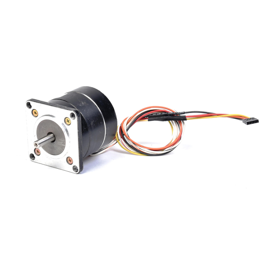
5-Phase Stepping Motor Unit
CFK II Series
Photocoupler Input
OPERATING MANUAL
Thank you for purchasing an Oriental Motor product.
This Operating Manual describes product handling procedures and safety precautions.
• Please read it thoroughly to ensure safe operation.
• Always keep the manual where it is readily available.
Introduction .......................................................... Page 2
Safety precautions ............................................... Page 3
Preparation .......................................................... Page 6
Checking the product ...................................... Page 6
Names and functions of parts ......................... Page 7
Main specifications .......................................... Page 8
Installation ............................................................ Page 11
Location for installation ................................... Page 11
Installing the motor .......................................... Page 12
Installing a load ............................................... Page 13
Overhung load and thrust load ........................ Page 14
Installing the driver .......................................... Page 15
Connection ........................................................... Page 16
Terminal blocks ................................................ Page 16
Connecting the motor ...................................... Page 16
Connecting to the power supply ...................... Page 16
Connecting the I/O signals .............................. Page 17
Terminal blocks pin assignments .................... Page 17
Connecting the CFK513-type motor ............... Page 18
Connection examples ...................................... Page 19
Explanation of I/O signals ............................... Page 20
Timing chart ..................................................... Page 24
Setting .................................................................. Page 25
Step angle ....................................................... Page 25
Motor current ................................................... Page 26
Pulse input modes ........................................... Page 29
Inspection ............................................................. Page 30
Troubleshooting and remedial actions ................. Page 31
Table of Contents
HP-4164-2
Advertisement
Table of Contents

Subscribe to Our Youtube Channel
Related Manuals for Vexta CFK II Series


Summary of Contents for Vexta CFK II Series
-
Page 1: Table Of Contents
HP-4164-2 5-Phase Stepping Motor Unit CFK II Series Photocoupler Input OPERATING MANUAL Table of Contents Introduction ............Page 2 Safety precautions ..........Page 3 Preparation ............Page 6 Checking the product ........Page 6 Names and functions of parts ......Page 7 Main specifications .......... -
Page 2: Introduction
Introduction Before using the motor unit Only qualified personnel should work with the product. Use the product correctly after thoroughly reading the section “Safety precautions.” The product described in this manual has been designed and manufactured for use in general industrial machinery, and must not be used for any other purpose. For the driver’s power supply, use a DC power supply with reinforced insulation on its primary and secondary sides. -
Page 3: Safety Precautions
Applicable standards (Recognized by UL for CSA standards) Applicable standards Certification body Standard file No. UL1004, UL519 Stepping CSA C22.2 No.77 File No. E64199 motor CSA C22.2 No.100 Driver • PK513, PMM3 H, PK54 , PK56 H and PK59 do not comply with CSA standards. •... - Page 4 Warning General • Do not use the product in explosive or corrosive environments, in the presence of flammable gases, locations subjected to splashing water, or near combustibles. Doing so may result in fire or injury. • Assign qualified personnel the task of installing, wiring, operating/controlling, inspecting and troubleshooting the product.
- Page 5 Caution General • Do not use the motor and driver beyond their specifications, or injury or damage to equipment may result. • Do not touch the motor or driver’s heat sink during operation or immediately after stopping. The surfaces are hot and may cause a burn. Transportation •...
-
Page 6: Preparation
Preparation This section covers the points to be checked along with the names, functions and main specifications of the respective parts. Checking the product Upon opening the package, verify that the items listed below are included. Report any missing or damaged items to the branch or sales office from which you purchased the product. -
Page 7: Names And Functions Of Parts
Names and functions of parts This section covers the names and functions of parts in the driver and motor. Driver Illustration shows the DFC5128T. Heat sink Mounting holes Mounting cutout Power-supply terminal block (TB1) Pulse input mode selector switch (1P/2P) Switches between 1-pulse input mode Motor terminal block (TB2) and 2-pulse input mode. -
Page 8: Main Specifications
Main specifications This section covers the main specifications. Refer to the catalog for detailed specifications and torque characteristics. Motor specifications Standard type PK513PA PMM33AH2 PMM35AH2 PK543NAWA PK544NAWA Motor Single shaft PK513PB PMM33BH2 PMM35BH2 PK543NBWA PK544NBWA model Double shaft Maximum holding 3.12 (0.022) 4.6 (0.033) 8.5 (0.06) - Page 9 High-speed type PK566H-NAA PK569H-NAA PK596-NAA PK599-NAA PK5913-NAA Motor Single shaft PK566H-NBA PK569H-NBA PK596-NBA PK599-NBA PK5913-NBA model Double shaft Maximum holding 117 (0.83) 230 (1.66) 290 (2.1) 580 (4.1) 890 (6.3) torque oz-in (N·m) Rotor inertia 1.53 14.8 oz-in (kg·m (280 × 10 (560 ×...
- Page 10 Driver specifications DFC5103T DFC5107T DFC5114T DFC5128T Driver model Power input voltage 24 VDC ±10% Excitation mode Microstep (Maximum 250 divisions) Photocoupler input Signal voltage Photocoupler ON: +4.5 to +5 V Input signal Photocoupler OFF: 0 to +1 V PLS, DIR: 5 VDC, 20 mA maximum, Input resistance 220 Ω A.W.OFF, C/S: 5 VDC, 15 mA maximum, Input resistance 470 Ω...
-
Page 11: Installation
Installation This section covers the environment and method of installing the motor and driver, along with load installation. Location for installation The motor and driver are designed and manufactured for installation in equipment. Install them in a well-ventilated location that provides easy access for inspection. The location must also satisfy the following conditions: •... -
Page 12: Installing The Motor
Installing the motor Direction of installation The motor can be installed in any direction. How to install the motor Install the motor onto an appropriate flat metal plate having excellent vibration resistance and heat conductivity. When installing the motor, secure it with four bolts (not supplied) through the four mounting holes provided. -
Page 13: Installing A Load
Installing a load When connecting a load to the motor, align the centers of the motor’s output shaft and load shaft. Direct coupling Align the centers of the motor’s output shaft and load shaft in a straight line. Using a belt drive Align the motor’s output shaft and load shaft in parallel with each other, and position both pulleys so that the line connecting their centers is at a right angle to the shafts. -
Page 14: Overhung Load And Thrust Load
Overhung load and thrust load The overhung load on the motor’s output shaft must be kept under the permissible values listed below. The thrust load must not exceed the motor’s mass. [Unit: lb. (N)] Overhung load Distance from the tip of motor’s output shaft [inch (mm)] Motor model 0 (0) 0.2 (5) -
Page 15: Installing The Driver
Installing the driver Installation method Install the driver on a flat metal plate having superior capacity to withstand vibration as well as a high heat-conductance effect. Always install the driver using the driver’s installation holes and install and fasten it either vertically or horizontally with the two screws (M3;... -
Page 16: Connection
Connection This section covers the methods of connecting the driver, motor, power and controller, as well as the connection examples and I/O interface. Terminal blocks Screw terminals are used. Remove the insulation from the core, then insert the core into the terminal and tighten with terminal screws. -
Page 17: Connecting The I/O Signals
Connecting the I/O signals Connecting the I/O wires into the driver’s I/O signal terminal blocks (TB3). Note • For the I/O signal cable, use twisted pair with a diameter equivalent to at least AWG24 to 22 (0.2 to 0.34 mm ). -
Page 18: Connecting The Cfk513-Type Motor
CFK513 CFK513 Connecting the CFK513 CFK513 CFK513-type motor The CFK513-type motors are of the connector type having no leads. To connect these motors, use the supplied motor cable. The applicable connector housing/contact, crimping tool and connector configuration are shown below. Connector housing/contact, crimping tool Connector housing MOLEX 51065-0500... -
Page 19: Connection Examples
Connection examples Examples of connections with the motor, power supply and controller are shown below. Driver 24 VDC ±10% Connector terminal No. Motor lead color -type) (Lead-type) Blue Orange Green Black Controller Controller (PNP-type) (NPN-type) +5 V +5 V 220 Ω PLS+ PLS- 220 Ω... -
Page 20: Explanation Of I/O Signals
Explanation of I/O signals Input signals The signal states indicate the state of the internal photocoupler (ON: power conducted; OFF: power not conducted). PLS input and DIR input This driver can select either 1-pulse input mode or 2-pulse input mode as the pulse-input mode to match the controller used. - Page 21 2-pulse input mode The controller’s CW pulses are connected to the CW+ (pin No.1) or the CW- (pin No.2), while the CCW pulses are connected to the CCW+ (pin No.3) or the CCW- (pin No.4). NPN-type PNP-type +5 V +5 V CCW+ 1, 3 1, 3...
- Page 22 A.W.OFF (All Windings Off) input This is used to rotate the motor’s output shaft and adjust its position. Warning • Do not turn the A.W.OFF (All Windings Off) input to “ON” while the motor is operating. The motor will stop and lose its holding ability, which may result in injury or damage to the equipment.
- Page 23 Output signals The driver’s output signals are photocoupler/opencollector outputs. The signal states indicate the state of the internal photocoupler (ON: power conducted; OFF: power not conducted). Timing (excitation timing) output When the motor-excitation state (combined phases of current flowing) is the excitation home position (step [0]), the driver switches on the timing output.
-
Page 24: Timing Chart
Timing chart 2-pulse input 1-pulse input All windings off All windings off Motor Motor * * Power input Power input 1 µs min. 1 µs min. CW input PLS input * * 100 ms 1 ms min. 100 ms 1 ms min. 0 s min. -
Page 25: Setting
Setting This section describes the methods for setting the step angle and motor’s current setting and switching the pulse-input mode. Step angle When setting the motor’s step angle, use the step-angle setting switches (DATA1 and DATA2). Factory settings DATA1 [0: 0.72°], DATA2 [0: 0.72°] •... -
Page 26: Motor Current
Motor current When the load is light and there is a margin for motor torque, the motor’s running vibration and the temperature increase of the motor and driver can be held down by lowering the motor’s running current and stop current. When adjusting the motor current, use the motor-run current-adjustment control (RUN) and motor-stop current-adjustment control (STOP). - Page 27 Adjusting the motor’s run current 1. Turn the DC check switch to the “ON.” 2. Switch on the driver’s power supply. DC check switch 3. Turning the motor’s run-current adjustment Factory setting [OFF] control in the counter-clockwise direction reduces the current. One-half the value displayed on the ammeter is the current per phase of the motor.
- Page 28 Adjusting the motor’s stop current 1. Turn the DC check switch to the “OFF.” 2. Switch on the driver’s power supply. 3. Turning the motor’s stop-current adjustment control in the counter-clockwise direction reduces the current. One-half the value displayed on the ammeter is the current per phase of the motor.
-
Page 29: Pulse Input Modes
Pulse input modes Set the pulse-input mode switch to either 1-pulse input mode or 2-pulse input mode, whichever the controller uses. Note Set the pulse-input mode switch when the driver power is off. Factory setting [1P: 1-pulse input mode] Pulse-input mode selector switch Setting 1-pulse input mode When operating the motor with pulse input and rotation-direction input, switch the pulse- input mode selector switch to the “1P”. -
Page 30: Inspection
Inspection It is recommended that periodic inspections be conducted for the items listed below after each operation of the motor. If an abnormal condition is noted, stop the use and contact your nearest office. Inspection Items • Are the motor installation screws loose? •... -
Page 31: Troubleshooting And Remedial Actions
Troubleshooting and remedial actions During motor operation, the motor or driver may fail to function properly due to an improper speed setting or wiring. When the motor cannot be operated correctly, refer to the contents provided in this section and take appropriate action. If the problem persists, contact your nearest office. - Page 32 Phenomenon Possible cause Remedial action Error in the motor’s cable Double-check that the driver and connection motor connections are correct. Current-adjustment control incorrectly set Return the current-adjustment controls If the setting is too low, the Motor operation to its factory setting and check. motor torque will also be too low is unstable.
- Page 33 Phenomenon Possible cause Remedial action The centers of the motor’s Check the linkage state for the motor’s output shaft and load shaft are output shaft and load shaft. not aligned. If changing the running pulse speed reduces the vibration, the motor is Motor resonating resonating.
- Page 36 • Unauthorized reproduction or copying of all or part of this instruction manual is prohibited. If a new copy is required to replace an original manual that has been damaged or lost, please contact your nearest branch or sales office. •...
Need help?
Do you have a question about the CFK II Series and is the answer not in the manual?
Questions and answers