Advertisement
Table of Contents
- 1 Table of Contents
- 2 Safety Precautions
- 3 Product Verification
- 4 Names and Function of Driver Parts
- 5 Installation
- 6 Driver Function Swithces
- 7 Input/Output Signals
- 8 Connections
- 9 Motor Current Adjustment
- 10 Troubleshooting
- 11 Specifications
- 12 Installing and Wiring in Compliance
- 13 With EMC Directive
- Download this manual
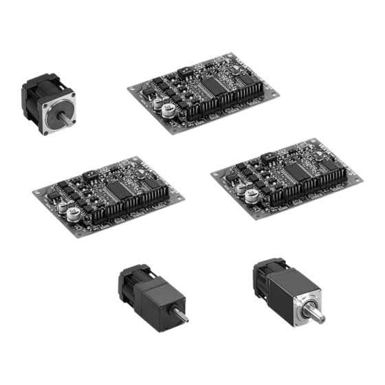
Compact & Lightweight Stepping Motor and Driver Package
PMC Series
• Standard Type
• MG Geared Type
• Harmonic Geared Type
OPERATING MANUAL
Thank you for purchasing an Oriental Motor product.
This Operating Manual describes product handling procedures and safety precautions.
• Please read it thoroughly to ensure safe operation.
• Always keep the manual where it is readily available.
Table of Contents
Safety precautions ................................. Page 2
Product verification ................................ Page 5
Names and function of driver parts ....... Page 7
Installation .............................................. Page 9
Driver function swithces ........................ Page 15
Input/output signals ............................... Page 16
Connections ........................................... Page 22
Motor current adjustment ...................... Page 24
Troubleshooting ..................................... Page 27
Specifications ......................................... Page 30
Installing and wiring in compliance ........ Page 33
HP-7420-4
1
Advertisement
Table of Contents

Subscribe to Our Youtube Channel
Related Manuals for Vexta PMC Series


Summary of Contents for Vexta PMC Series
-
Page 1: Table Of Contents
HP-7420-4 Compact & Lightweight Stepping Motor and Driver Package PMC Series • Standard Type • MG Geared Type • Harmonic Geared Type OPERATING MANUAL Table of Contents Safety precautions ......... Page 2 Product verification ........ Page 5 Names and function of driver parts ..Page 7 Installation .......... -
Page 2: Safety Precautions
Safety precautions Only qualified personnel should work with the product. Use the product correctly after thoroughly reading the section “Safety precautions.” The precautions described below are intended to prevent danger or injury to the user and other personnel through safe, correct use of the product. Use the product only after carefully reading and fully understanding these instructions. - Page 3 Operation • Turn off the driver power in the event of a power failure, or the motor may suddenly start when the power is restored and may cause injury or damage to equipment. • When you want to use the motor in a vertical application, take position holding measures.
- Page 4 Operation • Use a motor and driver only in the specified combination. An incorrect combination may cause a fire. • To avoid injury, remain alert during operation so that the motor can be stopped immediately in an emergency. • Before supplying power to the driver, turn all control inputs to the driver to “OFF.” Otherwise, the motor may start suddenly and cause injury or damage to equipment.
-
Page 5: Product Verification
Do not take the product out of the protective bag until ready to use it. Otherwise, the driver may be damage. Model numbers and motor/driver combinations The PMC series is a combined package which includes a stepping motor and driver. This operating manual is designated for the following products. Package model number... - Page 6 Motor frame size 3:28mm (1.1in.) sq. Compact & lightweight stepping motor and driver package PMC series P M C 3 3 A 1 - M G 3.6 P M C 3 3 A 1 - M G 3.6 P M C 3 3 A 1 - M G 3.6 P M C 3 3 A 1 - M G 3.6...
-
Page 7: Names And Function Of Driver Parts
Names and functions of driver parts Illustration shows the view from the connector side. STEPPING DRIVER VEXTA ① POWER CW/P. ② CCW/D. ⑥ C.OFF ③ STOP C.UP ⑦ ④ ⑤ ⑧ 24 / 36V ⑨ LED indications Indication LED name... - Page 8 Terminals Page Indication Terminal name Function reference ⑥ SIGNAL 1 The pulse mode signal is input to this (Pulse/CW Pulse 6-173977-8 terminal. The direction of the motor’s CW/P.+ Signal Input (AMP) rotation is determined by the following Terminal) ∗1 rotation direction input terminal. Page16, 17 (Pulse/CW Pulse The selection of...
-
Page 9: Installation
Installation Motor installation Motor installation location To prevent motor damage, install in a location with the following conditions. • Indoors (The motor is designed and manufactured to be used as an internal component within other equipment.) • Ambient temperature range -10°C~+50°C (+14°F~+122°F) (non-freezing) For harmonic geared type: 0°C~+40°C (+32°F~+104°F) (non-freezing) •... - Page 10 PMC33A(B)1-MG 4-M2.5 P0.45 Spot facing or through hole for pilot M2.5 Cross recessed head machine screws with washer (attached) Ø3(.12)-4holes Mounting plate PMC33A(B)1-HG Spot facing or 4-M3 P0.5 through hole for pilot Spring washer Mounting plate Hexagonal Ø3.5(.14)-4holes socket screws The following hardware (not supplied) is needed to mount the motor.
- Page 11 Motor mounting plate dimensions [unit: mm (inch)] PMC3 A(B)3 Ø3(.12)-4holes Ø5.5(.22)min. R0.3(.01)max. Shaft hole +0.033 +.0013 1.5(.059)min. Ø22 Spot facing or through hole for pilot X’ 23±0.2(.9±.008) 2(.08)min. X-X’ PMC33A(B)1-MG Ø3(.12)-4holes Ø5.5(.22)min. R0.5(.02)max. Shaft hole 2(.08)min. Ø11.5(.45) Spot facing or through hole for pilot 2(.08)min.
- Page 12 Connecting the motor to the drive mechanism (Load) Stepping motor Proper alignment is necessary when Coupling connecting the drive mechanism (load) to Ball screw the motor shaft. Use a flexible coupling. Note • Inadequate alignment may reduce the life span of the motor bearings or damage the motor shaft.
- Page 13 Driver installation Driver installation location To prevent driver damage, install in a location with the following conditions. • Indoors (The driver is designed and manufactured to be used as an internal component within other equipment.) Ambient temperature range 0°C~+40°C (+32°F~+104°F) (non-freezing). Install a forced-air cooling fan if ambient temperatures exceed +40°C (+104°F).
- Page 14 Driver mounting plate dimensions Horizontal mounting Vertical mounting Connector Securing the driver 1. Insert spring washers and M3 screws from the surface of the connector side of the circuit board. 2. Insert the spacer between the driver and the mounting plate, and secure by using M3 nuts.
-
Page 15: Driver Function Swithces
Driver function switches The driver has various operation functions which are set with the function switches. Step angle switch Pulse input mode switch ∗The white square section of the function switch represents the switch lever. Step angle switch (Factory setting : F) When the switch is set to: “F”... -
Page 16: Input/Output Signals
Input/output signals Input signals The input signals to the driver and their functions are specified below. Pulse/CW pulse signals Rotation direction/CCW pulse signals The diagram below shows the input circuits and an example connection to a controller. The number within refers to the pin Driver input (Internal circuit) - Page 17 Relation to the pulse input mode switch When the switch is set to the 1P position, motor rotation is controlled by pulse signals and rotation direction signals. When the switch is set to the 2P position, motor rotation is controlled by CW pulse signals and CCW pulse signals.
- Page 18 All windings off signal The diagram below shows the input circuit and an example connection to a controller. The number within refers to the pin Driver input number of driver connector SIGNAL 1. (Internal circuit) Controller output Open collector 220Ω +...
- Page 19 Manual detection of the home position Input the all windings off signal, set the motor to the desired position, then release the all windings off signal. All windings off signal input All windings off Home position signal release Photocoupler ON All windings off signal input Photocoupler OFF...
- Page 20 Automatic current cutback release signal The diagram below shows the input circuit and an example connection to a controller. The number within refers to the pin Driver input Controller output (Internal circuit) number of driver connector SIGNAL 2. Open collector 220Ω...
- Page 21 Output signals The output signals from the driver and their functions are specified below. Excitation timing signal The diagram below shows the output circuit and an example connection to a controller. The number within refers to the pin Driver input Controller output (Internal circuit) number of driver connector SIGNAL 2.
-
Page 22: Connections
Connections Connecting the motor, driver and power supply • For signal lines, use twisted pair wire of AWG28 (0.08mm ) or greater, and 1m (39.4in.) or less in length. • For power lines and when extending the motor lead wires use wires of AWG26 (0.14mm or greater. - Page 23 Example connections Connection to user’s controller User’s controller (+5V〜24V) Driver( ) ① Pulse/CW pulse signal input CW / P. ② ③ Rotation direction/ CCW / D. CCW pulse signal input ④ ⑤ All windings off signal input C.OFF ⑥ ⑦ Step angle signal input F / H ⑧...
-
Page 24: Motor Current Adjustment
Motor current adjustment The PMC driver is shipped with the motor rated current set to 0.35A/phase (and the standstill current reduction (current cutback) ratio set to approximately 50%). It is not necessary to adjust the current under normal operating conditions. However, readjust the current setting in the following cases. - Page 25 Adjusting the current using an ammeter When more precise current adjustment are necessary, make them by connecting an ammeter between the driver and motor, as shown below. Custom driver ( (This power supply is not RUN potentiometer needed when setting only the Used to adjust the standstill current.) motor’s running current...
- Page 26 Setting the motor standstill current 1. Confirm that the step angle switch set to F. 2. Check that nothing is connected or input to the C.UP terminal, and that the SW1 switch is turned off when using the connection shown above. 3.
-
Page 27: Troubleshooting
Troubleshooting Consult the following chart if the motor is not functioning properly. If the motor is still not functioning properly after confirming the checkpoints below, contact your nearest sales office as listed at the back of this manual. Problem Check points Measures 1. - Page 28 Check points Measures Problem 7. In 2-pulse input mode Connect the CW pulse signal line to the (pulse input mode switch pulse/CW pulse signal input terminal, and in the 2P position) are the connect the CCW pulse signal line to the CW and CCW pulse signal rotation direction/CCW pulse signal input lines connected...
- Page 29 Problem Check points Measures 12.Does the step angle Check the setting of the step angle switch required by your located on the driver. equipment match the step The motor rotates too angle of the stepping far or not far enough. motor? 13.Is the number of pulses set Check the controller pulse setting.
-
Page 30: Specifications
Specifications PMC33A3 PMC35A3 Single Shaft Package Model PMC33B3 PMC35B3 Double Shaft 0.033 (4.58) 0.06 (8.33) Maximum Holding Torque N·m (oz-in) 9×10 (0.05) 18×10 (0.099) Rotor Inertia kg·m (oz-in A/phase Rated Current 0.35 Basic Step Angle 0.72° mm (inch) 0.05 (0.002) T.I.R. at top of output shaft Shaft Runout Perpendicularity mm (inch) - Page 31 PMC33A1-MG3.6 PMC33A1-MG7.2 PMC33A1-MG10 PMC33A1-MG20 PMC33A1-MG30 PMC33A1-MG50 Single Shaft Package Model PMC33B1-MG3.6 PMC33B1-MG7.2 PMC33B1-MG10 PMC33B1-MG20 PMC33B1-MG30 PMC33B1-MG50 Double Shaft Maximum Holding Torque N·m (oz-in) 0.08 (11.1) 0.16 (22.2) 0.21 (29.1) 0.34 (47.2) 0.51 (70.8) kg·m (oz-in 9×10 (0.05) Rotor Inertia Rated Current A/phase 0.35 Basic Step Angle...
- Page 32 PMC33A1-HG50 PMC33A1-HG100 Single Shaft Package Model PMC33B1-HG50 PMC33B1-HG100 Double Shaft Maximum Holding Torque N·m (oz-in) 1.5 (213) 2.0 (284) kg·m (oz-in 12×10 (0.066) Rotor Inertia Rated Current A/phase 0.35 Basic Step Angle 0.0144° 0.0072° Gear Ratio 50:1 100:1 1.5 (213) 2.0 (284) Permissible Torque N·m (oz-in)
-
Page 33: Installing And Wiring In Compliance
Installing and wiring in compliance with EMC directive Introduction The EMC directive (89/336EEC and 92/31/EEC) Stepping motors from ORIENTAL MOTOR are designed to be a built in component. The EMC directive requires that the customer’s equipment incorporated with this product should comply with the EMC directive. - Page 34 Connection of mains filter for power line To prevent the noise generated from the driver being transferred to the outside through the power supply transformer, connect a mains filter to the AC input line of the power supply transformer. Use FN250-12/07 by Schaffner Electronik AG, 10ESK1 by CORCOM, ZAG2210-11S by TDK or their equivalent as the mains filter.
- Page 35 Others • To ensure that potential difference will not occur between the motor/driver and peripheral control system equipment, earth the cable directly to the grounding point. • When the relay and magnetic switch are used together, make sure that the surge is absorbed by the mains filter and CR circuit.
- Page 36 • Unauthorized reproduction or copying of all or part of this operating manual is prohibited. If a new copy is required to replace an original manual that has been damaged or lost, please contact your nearest branch or sales office. •...
Need help?
Do you have a question about the PMC Series and is the answer not in the manual?
Questions and answers