Table of Contents
Advertisement
Quick Links
Advertisement
Table of Contents

Subscribe to Our Youtube Channel
Related Manuals for CompuLab Tensor-I22


Summary of Contents for CompuLab Tensor-I22
- Page 1 Owner’s Manual Revision 1.2 Oct-2022...
-
Page 2: Safety Instructions
Damage due to servicing, that is not authorized by Compulab, is not covered by your warranty. Read and follow the safety instructions that came with the product. -
Page 3: Table Of Contents
INIMUM REQUIREMENTS -I22 ..............9 DENTIFYING ENSOR CONFIGURATION OPENING TENSOR-I22 ..................10 INSTALLING RAM ....................11 M.2 COOLING PLATE AND NVME/SATA ............. 12 OPTIONAL WIFI/BT MODULE ................14 CONNECTING TENSOR-I22 ................. 17 ENTERING BIOS SETUP ..................17 INSTALLING AND BOOTING OPERATING SYSTEM ..........17 SERVICE ...................... -
Page 4: Introduction
Tel: +972-48-290-168 | Fax: +972-48-325-251 | www.fit-iot.com Introduction Thank you for purchasing Tensor-I22. It is a fanless PC designed to be tough, capable, versatile and user-friendly. With proper installation, we expect Tensor-I22 to serve you for many years. The unique fanless design of Tensor-I22 eliminates the need for any maintenance after installation. -
Page 5: Specifications
200 mm X 200 mm X 35.3 mm for standard housing Characteristics Mounting Side/bottom VESA / DIN Rail mount Notes: 1. Some expansion TELs require a larger housing 2. Additional options are available with extension TELs www.fit-iot.com Page 5 of 19 Tensor-I22 owner’s manual... -
Page 6: Dimensions
Isolated CAN bus port TRIP1 / TRIP2 / int. USB FT.Q-CAN 4 – 20 isolated GPIOs TRIP1 / TRIP2 / int. USB FT.S-GPIO FT.V-TERM4 Terminal block 4x for FT.S-GPIO 4 per FT.S-GPIO FT.S-GPIO www.fit-iot.com Page 6 of 19 Tensor-I22 owner’s manual... - Page 7 TRIP1 FT.U-POE2 802.3at Type 1 by RJ45 2 x SFP+ socket for optical GbE TRIP1 FT.W-OPLN2 connection Notes: This interface is also available in some quantity on the motherboard, without a TEL. www.fit-iot.com Page 7 of 19 Tensor-I22 owner’s manual...
-
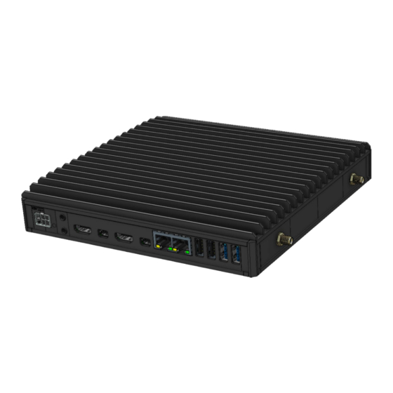
Page 8: Connectors Layout
Hayetsira St. 17, Yokneam, Israel Tel: +972-48-290-168 | Fax: +972-48-325-251 | www.fit-iot.com Connectors layout Back view Front view www.fit-iot.com Page 8 of 19 Tensor-I22 owner’s manual... -
Page 9: Quick Start Guide
Tensor-I22 configuration is detailed on the label attached to the bottom side of the computer. Note Pay attention to RAM and storage. If not installed, Tensor-I22 will not boot. You will have to install these devices firstly. www.fit-iot.com Page 9 of 19... -
Page 10: Opening Tensor-I22
Hayetsira St. 17, Yokneam, Israel Tel: +972-48-290-168 | Fax: +972-48-325-251 | www.fit-iot.com Opening Tensor-I22 You will need to open Tensor-I22 in order to install RAM, storage, modem, WiFi module, RTC battery or extensions. Required tool: Phillips screwdriver. To open Tensor-I22 please follow these steps: Place Tensor-I22 on a flat surface bottom-up. -
Page 11: Installing Ram
Hayetsira St. 17, Yokneam, Israel Tel: +972-48-290-168 | Fax: +972-48-325-251 | www.fit-iot.com Installing RAM Tensor-I22 can accept two SODIMM DDR4 modules Insert DDR4 SODIMM module and press it down until it is latching firmly on both sides www.fit-iot.com Page 11 of 19... -
Page 12: M.2 Cooling Plate And Nvme/Sata
Press the NVMe/SSD firmly until its connector edge is seated between the alignment pins and rests on fastening screw. Once positioned correctly the connector edge should stick out above the edge of the M.2 cooling plate. Tighten the spacer screws www.fit-iot.com Page 12 of 19 Tensor-I22 owner’s manual... - Page 13 After correct positioning, the holes in the plate align with the spacers on the board. Hold down the M.2 cooling plate and tighten the 3 panel screws Use the Philips screwdriver for closing the bottom cover back. www.fit-iot.com Page 13 of 19 Tensor-I22 owner’s manual...
-
Page 14: Optional Wifi/Bt Module
Tel: +972-48-290-168 | Fax: +972-48-325-251 | www.fit-iot.com Optional WiFi/BT Module WiFi module is not installed by default. Installing WiFi/BT module 1. Unscrew the side frame(s) as shown below 2. Remove the frame(s) www.fit-iot.com Page 14 of 19 Tensor-I22 owner’s manual... - Page 15 4. Assembly back the frame and tighten it with screws 5. Remove the bottom cover by unscrewing 4 screws as shown in the picture above www.fit-iot.com Page 15 of 19 Tensor-I22 owner’s manual...
- Page 16 7. Press it down until latching the spacer. 8. Tighten the fastening screw. 9. Connect the wire edges of the antenna connectors to the appropriate connectors on the WiFi/BT module. Assembly back the bottom cover www.fit-iot.com Page 16 of 19 Tensor-I22 owner’s manual...
-
Page 17: Connecting Tensor-I22
Insert the DC plug into the Tensor-I22 DC-in jack. Rotate clockwise 90° to secure. Slide into the power-supply the AC blade correct to your country and plug the power-supply into an AC- outlet. The power button on Tensor-I22 should turn green, in a few seconds an image should appear on the display. -
Page 18: Service
Compulab guarantees products against defects in workmanship and material for a period of 60 months from the date of shipment. • Your sole remedy and Compulab’s sole liability shall be for Compulab, at its sole discretion, to either repair or replace the defective product at no charge. •... - Page 19 Statement technician for help. Changes or modifications to this equipment not expressly approved by the party responsible for compliance (Compulab Ltd.) could void the user’s authority to operate the equipment WEEE This symbol means that you must dispose of an...
Need help?
Do you have a question about the Tensor-I22 and is the answer not in the manual?
Questions and answers