Table of Contents
Advertisement
Quick Links
Advertisement
Table of Contents

Related Manuals for CompuLab Trim-Slice


Summary of Contents for CompuLab Trim-Slice
- Page 1 Trim-Slice User’s Guide...
-
Page 2: Table Of Contents
Trim-Slice Overview .......... 6 Front View ..........6 Rear View ..........6 Side View ........... 7 Getting started with Trim-Slice ......8 Connecting a display ......... 8 Connecting keyboard and mouse ....8 Connecting power ........9 Turning on the system ......10 System login .......... - Page 3 Power LED..........11 Audio ............11 Serial port ..........12 Micro-SD card .......... 12 Video input ..........13 Wireless USB adapters ......13 Trim-Slice Software ......... 14 General ............ 14 Boot-loader ..........14 System recovery ........15 July 2011...
-
Page 4: Package Contents
Power supply AC blade HDMI to DVI adapter cable Mini serial to DB-9 adapter cable 3.5mm to RCA adapter cable WiFi antenna User’s guide Optional item. Availability depends on Trim-Slice model configuration. July 2011... -
Page 5: Trim-Slice Features
Composite analog NTSC / PAL WiFi 802.11n, modular Bluetooth Bluetooth V2.1+EDR, modular Ethernet 1000 BaseT Ethernet 4 ports USB 2.0 480Mbps Full-size SD socket, SDHC Micro-SD socket, SDHC Serial RS232 Power 12V DC Optional feature. Availability depends on Trim-Slice model configuration. July 2011... -
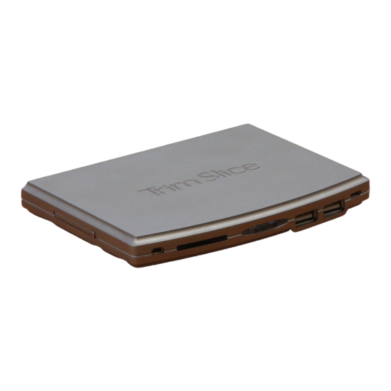
Page 6: Trim-Slice Overview
Trim-Slice Overview Front View R S -2 3 2 S D ca rd slo t P o w e r b u tto n U S B p o rts M icro U S B Rear View W iF i U S B... -
Page 7: Side View
Side View K e n s in g to n lo ck M icro -S D R e co ve ry-b o o t s lo t b u tto n July 2011... -
Page 8: Getting Started With Trim-Slice
Getting started with Trim-Slice Connecting a display HDMI display Connect the display to the Trim-Slice HDMI primary display output using a standard HDMI cable. DVI display Connect the display to the Trim-Slice HDMI primary display output using a standard DVI cable and the HDMI to DVI adapter included in this package. -
Page 9: Connecting Power
Connecting power Insert the AC power-supply blade into the power supply unit. Insert the power supply plug into the Trim-Slice power jack. Turn the power plug clock-wise to lock the plug. July 2011... -
Page 10: Turning On The System
Turning on the system Plug the power supply unit into an AC outlet. Trim-Slice will turn on and boot. System login Log into the O/S using the following user details: Username: trim Password: 111111 July 2011... -
Page 11: Using Trim-Slice
Using Trim-Slice Power button The Trim-Slice power button controls the system power state. Pressing the button for more than 5 seconds, shuts down the system. When the system is shut down, pressing the power button turns on the Trim-Slice. Power LED The Trim-Slice power LED indicates the system power state. -
Page 12: Serial Port
Serial port Use the mini serial to DB-9 adapter included in this package and a standard null-modem cable to connect the Trim-Slice RS- 232 port to a PC serial port. Micro-SD card Open the micro-SD security door screw shown below. Open the security door. -
Page 13: Video Input
Video input The Trim-Slice video input is implemented on the additional pin of the line-out audio jack. Use the 3.5mm to RCA adapter included in this package and a standard RCA cable to connect the Trim-Slice to an external analog video source. -
Page 14: Trim-Slice Software
Trim-Slice Software General The Trim-Slice is a flexible and software-open platform supporting a variety of operating systems. For further information and documentation please visit http://trimslice.com/web/support Boot-loader The Trim-Slice utilizes U-Boot as the system boot-loader responsible for initializing the system and loading the O/S. The U-Boot is a flexible, feature-rich, open-source boot-loader used in a broad range of embedded devices. -
Page 15: System Recovery
System recovery n case of firmware or O/S corruption, the Trim-Slice design allows full system recovery by using a downloadable recovery image and a standard SD card. For recovery instructions please refer to http://trimslice.com/web/support July 2011... - Page 16 -Reorient or relocate the receiving antenna. (CompuLab Ltd.) could void the user’s authority to operate the -Increase the separation between the equipment and receiver. equipment.
Need help?
Do you have a question about the Trim-Slice and is the answer not in the manual?
Questions and answers