
Subscribe to Our Youtube Channel
Related Manuals for Amazone Cirrus 03


Summary of Contents for Amazone Cirrus 03
- Page 1 Operating manual Large area seed drill Cirrus 03 Please read this MG6382 operating manual BAH0101.08 05.2022 before initial operation. Keep it in a safe place for future use.
- Page 3 + 49 (0) 5405 501-0 E-mail: amazone@amazone.de Spare Parts Order Spare parts lists are freely accessible in the spare parts portal at www.amazone.de. Please send orders to your AMAZONE dealer. Formalities of the operating manual Machine type: Cirrus 03 Document number: MG6382 Compilation date: 05.2022...
- Page 4 If there are any questions or problems, please read this operating manual or contact your local service partner. Regular maintenance and timely replacement of worn or damaged parts increases the service life of your implement. Cirrus 03 BAH0101.08 05.2022...
- Page 5 Required tractor equipment ....................63 4.12 Noise production data ......................63 Layout and function ................... 64 Control terminal for implements with ISOBUS system ............65 5.1.1 AMAZONE AmaTron 4 control terminal ................. 65 5.1.2 AMAZONE TwinTerminal ....................... 66 Cirrus 03 BAH0101.08 05.2022...
- Page 6 5.1.3 AMAZONE mySeeder app ....................66 Service brake system ......................67 5.2.1 Parking brake ........................67 5.2.2 Dual circuit pneumatic service brake system ................ 68 5.2.3 Hydraulic service brake system .................... 68 Implements without service brake system ................68 Storage compartment ......................69 Radar .............................
- Page 7 Coupling the T-Pack U ......................160 7.4.2 Coupling the Cirrus to the tractor ..................160 Uncoupling the implement ....................164 Connecting/disconnecting the PTO shaft driven hydraulic pump ........167 7.6.1 Connecting the hydraulic pump ................... 168 Cirrus 03 BAH0101.08 05.2022...
- Page 8 8.14 Exact following harrow ......................205 8.14.1 Moving the exact following harrow to the working / transport position ........ 205 8.14.2 Exact following harrow tine position ..................206 8.14.3 Exact following harrow pressure adjustment ..............206 Cirrus 03 BAH0101.08 05.2022...
- Page 9 Emptying the hopper and/or the metering unit ..............264 10.10.1 One-chamber hopper quick emptying .................. 264 10.10.2 Two-chamber hopper quick emptying .................. 265 10.10.3 Hopper residual emptying ....................266 10.10.4 Emptying the metering unit ....................266 Fault indications ..................267 Cirrus 03 BAH0101.08 05.2022...
- Page 10 Dismounting the TwinTeC+ seed line ................. 309 12.7.11 Check/replace the TwinTeC+ inner scraper ................ 309 12.7.12 Checking/replacing the TwinTeC+ seed catcher ..............310 12.7.13 Check/replace the TwinTeC+ baffle lip ................311 12.7.14 Check/replace the TwinTeC+ press roller ................312 Cirrus 03 BAH0101.08 05.2022...
- Page 11 Hydraulic diagram - Cirrus 6003-2(C)(CC)/RoTeC pro, part 1 ..........339 13.6.1 Hydraulic diagram - Cirrus 6003-2(C)(CC) RoTeC pro, part 2 ..........341 13.7 Hydraulic diagram - Cirrus 6003-2(C)(CC)/TwinTeC+, part 1 ..........343 13.7.1 Hydraulic diagram - Cirrus 6003-2(C)(CC)/TwinTeC+, part 2 ..........345 Cirrus 03 BAH0101.08 05.2022...
- Page 12 Cirrus 03 BAH0101.08 05.2022...
- Page 13 Numbers in round brackets refer to the item numbers in the illustrations. The first number refers to the diagram and the second number to the item. Example: (Fig. 3/6) = Figure 3 / Position 6 All the directions specified in the operating manual are always viewed in the direction of travel. Cirrus 03 BAH0101.08 05.2022...
- Page 14 If the user discovers that a function is not working properly, then they must eliminate this fault immedi- ately. If this is not the task of the user or if the user does not have the appropriate technical know- ledge, they should report this fault to their superior (operator). Cirrus 03 BAH0101.08 05.2022...
- Page 15 Non-compliance with the instructions in the operating manual regarding commissioning, opera- tion and maintenance Unauthorised design changes to the implement Insufficient monitoring of implement parts which are subject to wear Improperly executed repairs Disasters due to the effects of foreign objects and force majeure. Cirrus 03 BAH0101.08 05.2022...
- Page 16 Non-compliance with these instructions can cause faults on the implement or disturbance to the environment. NOTE Indicates handling tips and particularly useful information. These instructions will help you to use all the functions of your implement in the best way possible. Cirrus 03 BAH0101.08 05.2022...
- Page 17 As well as all the safety information in this operating manual, comply with the general, national regulations pertaining to accident prevention and environmental protection. When driving on public roads and routes you should comply with the statutory road traffic regulations. Cirrus 03 BAH0101.08 05.2022...
- Page 18 "Specialist workshop". The personnel of a specialist workshop shall possess the appropriate knowledge and suitable aids (tools, lifting and support equipment) for carrying out the maintenance and repair work on the implement in a way which is both appropriate and safe. Cirrus 03 BAH0101.08 05.2022...
- Page 19 It is strictly forbidden to drill holes in the frame or on the running gear increase the size of existing holes on the frame or the running gear weld on load-bearing parts. Cirrus 03 BAH0101.08 05.2022...
- Page 20 Immediately replace any implement parts which are not in a perfect state. Use only genuine AMAZONE spare and wear parts or the parts cleared by AMAZONEN-WERKE so that the operating permit retains its validity in accordance with national and international regulations. If you use wear and spare parts from third parties, there is no guarantee that they have been designed and manufactured in such a way as to meet the requirements placed on them.
- Page 21 Warning symbols on the implement Always keep all the warning symbols of the implement clean and in a legible state. Replace illegible warning symbols. You can request the warning symbols from your AMAZONE dealer using the order number (e.g., MD 075). Layout Warning symbols indicate danger areas on the implement and warn against residual dangers.
- Page 22 It is forbidden to stand in the swivelling range of the implement when implement parts are being lowered. Direct people out of the swivelling range of lowering implement parts before you lower the implement parts. Cirrus 03 BAH0101.08 05.2022...
- Page 23 110 up to 220 kV 4 m / 12.12 ft over 220 up to 380 kV 5 m / 16.40 ft MD 095 Before commissioning the machine read and observe the operating manual and the safety instructions carefully! Cirrus 03 BAH0101.08 05.2022...
- Page 24 3-point hitch when actuating the 3-point hydraulic system. Actuate the operator controls for the tractor's three-point hydraulic system only from the designated workstation under no circumstances if you are in the lifting area between the tractor and implement. Cirrus 03 BAH0101.08 05.2022...
- Page 25 These dangers can cause extremely serious and potentially fatal injuries. Maintain an adequate safety distance from moving implement parts while the tractor engine is running. Ensure that all personnel maintain an adequate safety distance from moving implement parts. Cirrus 03 BAH0101.08 05.2022...
- Page 26 Will cause serious injuries anywhere on the body or death. Secure the implement against moving away unintentionally before uncoupling the implement from the tractor. To do this, use the parking brake and/or the wheel chock(s). Cirrus 03 BAH0101.08 05.2022...
- Page 27 Direct people out of the danger area between the tractor and the implement whenever the engine of the tractor is running and the tractor is not secured against unintentional rolling. Cirrus 03 BAH0101.08 05.2022...
- Page 28 General Safety Information 2.13.1 Position of warning symbols The following figures show the arrangement of the warning symbols on the implement. Fig. 1 Fig. 2 Fig. 3 Fig. 4 Cirrus 03 BAH0101.08 05.2022...
- Page 29 General Safety Information Fig. 5 Fig. 6 Fig. 7 Fig. 8 Fig. 9 Fig. 10 Cirrus 03 BAH0101.08 05.2022...
- Page 30 Comply with the risk prevention instructions on the warning symbol. When driving on public roads and routes, comply with the appropriate statutory road traffic regulations. Cirrus 03 BAH0101.08 05.2022...
- Page 31 Drive in such a way that you always have full control over the tractor with the attached machine. In so doing, take your personal abilities into account, as well as the road, traffic, visibility and weather conditions, the driving characteristics of the tractor and the connected or coupled implement. Cirrus 03 BAH0101.08 05.2022...
- Page 32 The release ropes for quick couplings must hang loosely and may not release themselves when in lowered position! Always ensure that uncoupled implements are stable! Cirrus 03 BAH0101.08 05.2022...
- Page 33 Secure the tractor against unintentional start-up and rolling away before you leave the tractor. For this: Lower the implement onto the ground Apply the tractor parking brake Switch off the tractor engine Remove the ignition key. Cirrus 03 BAH0101.08 05.2022...
- Page 34 Adjust your forward speed to the prevailing conditions! Before driving downhill, switch to a lower gear! Before road transport, always switch off the independent wheel braking (lock the pedals)! Observe the maximum permissible total weight. Cirrus 03 BAH0101.08 05.2022...
- Page 35 Have the hydraulic hose lines checked by a specialist for proper functioning at least once a year! Replace the hydraulic hose lines if they are damaged or worn! Use only genuine AMAZONE hydraulic hose lines! The hydraulic hose lines should not be used for longer than six years, including any storage time of maximum two years.
- Page 36 Only a specialist workshop may adjust the height of the drawbar on clevis coupling drawbars with a drawbar load. Observe the national regulations for implements without a service brake system. Cirrus 03 BAH0101.08 05.2022...
- Page 37 Hydraulic service brake system for export implements Hydraulic service brake systems are not permitted in Germany. When filling up or replacing the brake fluid, only use the prescribed hydraulic fluids. When replacing the hydraulic fluids, comply with the appropriate regulations. Cirrus 03 BAH0101.08 05.2022...
- Page 38 After the PTO shaft is switched off, there is a risk of injury from the continued centrifugal mass of rotating implement parts. Do not approach the implement too closely during this time. You must only start work on the implement once all implement parts are at a complete standstill. Cirrus 03 BAH0101.08 05.2022...
- Page 39 Disconnect the cable to the tractor generator and battery, before carrying out electrical welding work on the tractor and on mounted implements! Spare parts must meet at least the technical requirements specified by AMAZONEN-WERKE! This is ensured through the use of genuine AMAZONE spare parts! Cirrus 03 BAH0101.08 05.2022...
- Page 40 The implement is generally delivered using a low-bed trailer. Attach the implement to a suitable tractor for loa- ding and unloading from the low-bed trailer, see section "Initial operation" section "Coupling and uncoupling the imple- ment" section "Road transport". Fig. 11 Cirrus 03 BAH0101.08 05.2022...
- Page 41 The adapter (Fig. 12/2) should only be used for loading the implement. Otherwise, the maximum back pressure of 10 bar/145.04 psi during operation would be exceeded, see section 6.3, page 144. The control terminal does not have to be connected. Cirrus 03 BAH0101.08 05.2022...
- Page 42 8. Uncouple the tractor from the implement. Fig. 14 The (Fig. 15) symbol marks the lashing points on the implement. Fig. 15 In Germany, the permitted total height of the loaded HGV is 4.0 m / 13.12 ft. Cirrus 03 BAH0101.08 05.2022...
- Page 43 5. Swivel the hydraulic cylinder (Fig. 16/1). Fig. 16 6. Fix the position of the hydraulic cylinder with the pin. Fig. 17 7. Lock the pin. Fig. 18 Cirrus 03 BAH0101.08 05.2022...
- Page 44 Otherwise keep twisting the valve pin (Fig. 19/1) until the valve pin re- leases and is inserted into the valve. Fig. 19 13. Disconnect the implement from the tractor, see section "Uncoupling the implement". Cirrus 03 BAH0101.08 05.2022...
- Page 45 Cirrus 4003 Cirrus 4003-C rigid Cirrus 4003-2 Cirrus 4003-2C foldable Cirrus 6003-2 Cirrus 6003-2C foldable Cirrus 4003-CC rigid FerTeC coulters Cirrus 4003-2CC foldable FerTeC coulters Cirrus 6003-2CC foldable FerTeC coulters Cirrus 3003 Compact Fig. 20 Cirrus 03 BAH0101.08 05.2022...
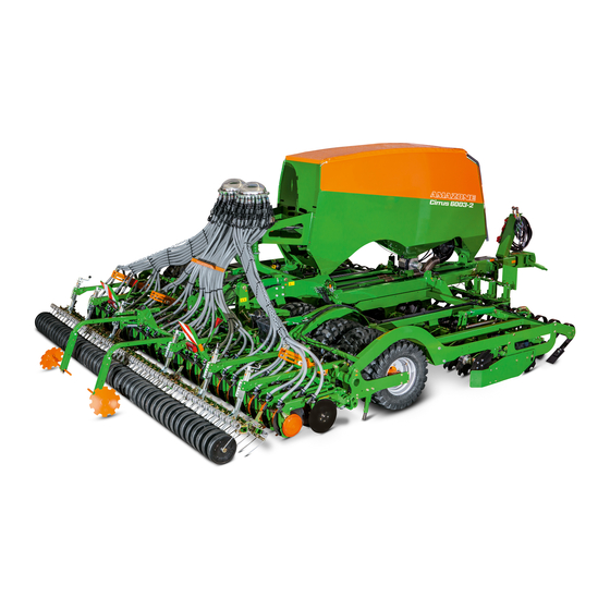
- Page 46 Product description Cirrus 4003-C Fig. 21 Cirrus 6003-2CC Fig. 22 Cirrus 03 BAH0101.08 05.2022...
- Page 47 (6) TwinTeC+ double disc coulter (1) Crushboard selectively in front of or behind the disc array (2) Track marker (3) RoTeC pro Control coulters (4) Roller harrow, optionally exact following harrow (5) Tramline marker Fig. 24 Cirrus 03 BAH0101.08 05.2022...
- Page 48 Overview of assembly groups Control terminal for implements with ISOBUS system, e.g. AmaTron 4 control terminal Fig. 25 (1) Hose cabinet (2) Tensioned crosspiece (3) Drawbar, extendable (4) Wheel mark eradicator Fig. 26 (1) Storage compartment Fig. 27 Cirrus 03 BAH0101.08 05.2022...
- Page 49 (2) Ascent with handle Fig. 28 Hopper cover for implements with two chamber system Fig. 29 (1) Low level sensor Fig. 30 Fan with oil cooler (oil cooler only in combination with power take-off) Fig. 31 Cirrus 03 BAH0101.08 05.2022...
- Page 50 Fig. 32 (1) Metering unit with injector for Cirrus 6003-2 with one-chamber system with 1 distributor head Fig. 33 (1) Metering unit with sluice for implements with two chamber system Fig. 34 Cirrus 03 BAH0101.08 05.2022...
- Page 51 Product description RoTeC pro Control coulter Fig. 35 TwinTeC+ double-disc coulter Fig. 36 FerTeC single-disc coulter Fig. 37 Cirrus 03 BAH0101.08 05.2022...
- Page 52 (1) Cirrus 6003-2 mechanical transport locking mechanism for the implement section. The mechanical transport locking mechanism on the Cirrus 4003-2 is not of the same design as the mechanical transport locking mechanism on the Cirrus 6003-2. Fig. 40 Cirrus 03 BAH0101.08 05.2022...
- Page 53 The function of the tractor control unit is represented symbolically: Latched, for a permanent oil circulation When the button is pressed, as long as the function is active Float position, free oil flow in the control unit Cirrus 03 BAH0101.08 05.2022...
- Page 54 Pressureless return flow (red T) Fan hydraulic motor, Important! Always connect this hydraulic line to section 6.3, page 144 the tractor. The connection of this hydraulic line to the tractor is required for all of the above-listed hydraulic func- tions. Cirrus 03 BAH0101.08 05.2022...
- Page 55 Depending on the implement equipment, the hydraulic system is protected by inline filters (Fig. 44/1) against dirt entering from the outside. This maintains the hydraulic function even when changing tractors frequently. The inline filters are maintenance-free. Fig. 44 Cirrus 03 BAH0101.08 05.2022...
- Page 56 Fig. 46 (1) 2 forwards-facing warning signs (2) 2 forwards-facing marker lights Fig. 47 (1) 2 x 3 reflectors, yellow, laterally with a max. spacing of 3 m Fig. 48 Cirrus 03 BAH0101.08 05.2022...
- Page 57 AMAZONE spare parts. Other uses to those specified above are forbidden and shall be considered as improper. For any damage resulting from improper use the operator bears sole responsibility AMAZONEN-WERKE accepts no liability.
- Page 58 In the area of the swivelling implement sections when unfolding and folding the implement sections near overhead power lines in the area of moving parts underneath raised, unsecured implements or parts of implements. Cirrus 03 BAH0101.08 05.2022...
- Page 59 (6) Perm. rear axle load kg/lb (7) Perm. system pressure bar/psi (8) Perm. total weight kg/lb Fig. 50 (9) Factory (10) Model year CE mark Information on the CE mark: (1) Year of manufacture Fig. 51 Cirrus 03 BAH0101.08 05.2022...
- Page 60 DIN 51524-2 ISO 68 [bar] Hydraulic system pressure [psi] 3045.79 Number of tyres on [number] rollers with integrated running gear Tyres AS tread 15.0/55-17.0 14PR Tyre matrix 400/55 R17.5 = Standard equipment = Optional equipment = Special equipment Cirrus 03 BAH0101.08 05.2022...
- Page 61 AS tread tyres 15.0/55-17.0 14PR Tyre matrix 400/55 R17.5 Number of tyres on T-Pack IN [number] (integrated) Number of tyres on T-Pack S (side) [number] = Standard equipment = Optional equipment = Special equipment Cirrus 03 BAH0101.08 05.2022...
- Page 62 [lb] 5511.55 6613.87 section 6.1.1.1, page 139 Max. permitted speed see section 9, page 223 In transport position, the filling auger does not change the total height of the implement Cirrus 03 BAH0101.08 05.2022...
- Page 63 The workplace-related emission value (acoustic pressure level) is 70 dB(A), measured in operating condition at the ear of the tractor driver with the cab closed. Measuring unit: OPTAC SLM 5. The noise level is primarily dependent on the vehicle used. Cirrus 03 BAH0101.08 05.2022...
- Page 64 The roller (Fig. 52/4) has an integrated running gear for road transport. Implements with swivelling sections can be folded for road transport. The GreenDrill seed drill (Fig. 52/11) is used for spreading catch crops, nurse crops, and re-seeding grassland. Cirrus 03 BAH0101.08 05.2022...
- Page 65 The ISOBUS system makes it possible to connect the implement to any ISOBUS control terminal. If the tractor has an ISOBUS system, the AMAZONE job computer can be connected to the existing ISOBUS socket of the tractor and operated with the on-board terminal.
- Page 66 The job computer must be equipped with the AMAZONE Bluetooth adapter. Download the mySeeder app onto your mobile device from the Fig. 55 App Store or Play Store.
- Page 67 Releasing the parking brake: Turn the crank to the left (L). Fig. 56 In the parking position, the crank (Fig. 57/1) is inserted in the transport bracket and secured with a linch pin (Fig. 57/2). Fig. 57 Cirrus 03 BAH0101.08 05.2022...
- Page 68 Before initial operation, check the officially approved registration of your implement without its own service brake system. Subsequently installed accessories change the axle load and may make it necessary to equip the implement with a service brake system. Cirrus 03 BAH0101.08 05.2022...
- Page 69 (Fig. 60). Other sources are also possible, refer to the control terminal operating manual. The working speed data is used to determine: the worked area (hectare counter) the required speed for the metering roller(s). Fig. 60 Cirrus 03 BAH0101.08 05.2022...
- Page 70 The cutting roller is auto- matically pre-tensioned using a hydraulic pres- sure accumulator (Fig. 62/2). A stop tap is atta- ched to the hydraulic pressure accumulator. The working intensity of the cutting roller can be adjusted. Fig. 62 Cirrus 03 BAH0101.08 05.2022...
- Page 71 The working intensity of the crushboard is ad- justed with stops (Fig. 65/1), which prevent the piston from retracting into the hydraulic cylinder. The maximum working intensity is achieved if no stop (Fig. 65/1) is resting against it. Fig. 65 Cirrus 03 BAH0101.08 05.2022...
- Page 72 Lengthen the side plate if required. The installation parts are found in the storage compartment on the implement. The holes (Fig. 68/3) are used to fasten the installation parts. The basic setting (factory setting) of the side plates is illustrated. Fig. 68 Cirrus 03 BAH0101.08 05.2022...
- Page 73 TwinTeC+ double-disc coulters is adjusted. both side plates in a vertical direction. When delivered, the outer discs are screwed in the basic position. The marking (Fig. 69/1) indicates the basic position. Fig. 69 Cirrus 03 BAH0101.08 05.2022...
- Page 74 TwinTeC+ double-disc coulters is adjusted. When delivered, the cutting discs are screwed in the basic position. The marking (Fig. 72/1) indicates the basic position. Side plates are not required. Fig. 72 Cirrus 03 BAH0101.08 05.2022...
- Page 75 The T-Pack S (Fig. 73/2) works in front of the booms. The T-Pack S can be used with Cirrus 4003-2 and Cirrus 6003-2, but not in conjunction with the wheel mark eradicator or crushboard in front of the disc array. Cirrus 03 BAH0101.08 05.2022...
- Page 76 (Fig. 75). Mounting at the front requires additional mounting parts. The procedures for mounting on the tractor and for operation can be found in the "T-Pack U" operating manual. Fig. 75 Cirrus 03 BAH0101.08 05.2022...
- Page 77 Fig. 76 Each tyre can have an adjustable scraper (Fig. 77/1). The distance between the tyres and the ad- justable scraper (Fig. 77/1) should not be less than 15 mm / 0.59 in. Fig. 77 Cirrus 03 BAH0101.08 05.2022...
- Page 78 Adjustable stone clearers (Fig. 80) prevent the stones from getting wedged. The stone clearers push the stones into the tyre track, where they are pressed into the soil when the tyre runs over them. Fig. 80 Cirrus 03 BAH0101.08 05.2022...
- Page 79 2 levers (Fig. 82/2) serve to adjust the furrow ridge levellers on the swivelling sections. The scale (Fig. 82/3) serves as orientation. Fig. 82 The furrow ridge levellers (Fig. 83/1) are adjusted at the centre of the implement with a crank. Fig. 83 Cirrus 03 BAH0101.08 05.2022...
- Page 80 The metering units (Fig. 85/3) are arranged be- hind each other. Fig. 85 When switching on the fan, pressure builds up in the hopper and conveyor section. The hopper covers (Fig. 86/1) seal the hopper pressure-tight. Fig. 86 Cirrus 03 BAH0101.08 05.2022...
- Page 81 The interior lighting (Fig. 88/1) of the hopper is coupled with the driving light of the tractor. Fig. 88 It is possible to carry reserve sacks (Fig. 89/1) on the charging sieves when the hopper cover is closed. Fig. 89 Cirrus 03 BAH0101.08 05.2022...
- Page 82 In terms of operation, a distinction is made between rigid and folding implements. The filling auger for a folding implement is shown. Fig. 91 Cirrus 03 BAH0101.08 05.2022...
- Page 83 Seed drills with one metering unit and one distributor head have 1 chamber in the hopper 1 metering unit (Fig. 93/1) 1 injector (Fig. 93/2) 1 single conveyor section (Fig. 93/3) 1 distributor head. Fig. 93 Cirrus 03 BAH0101.08 05.2022...
- Page 84 2 sluices (Fig. 96/2) 1 single conveyor section (Fig. 96/3) 1 distributor head. The spread rate is calibrated consecutively on both metering units. The order of the numbered metering units can be freely selected. Fig. 96 Cirrus 03 BAH0101.08 05.2022...
- Page 85 Fig. 98 a flap seals access to the right tube of the injector the seed quantity is not halved. Cirrus 03 BAH0101.08 05.2022...
- Page 86 When calibrating the spread rate and during operation the metered material flows out of the rear hopper chamber into the right conveyor tube to the FerTeC distributor head (Fig. 99/2a) the metered quantity is not halved during calibration. Fig. 101 Cirrus 03 BAH0101.08 05.2022...
- Page 87 The working speed is determined, e.g. by pulses from the radar or the tractor signal. can be increased in defined quantity increments during operation, e.g. when changing from nor- mal to heavy soils, by pressing a button on the control terminal. Cirrus 03 BAH0101.08 05.2022...
- Page 88 Fig. 104 The volume of some metering rollers can be modified by repositioning/removing the existing wheels and inserting metering wheels without chambers. Individual parts for conversion are found in the storage compartment of the implement. Fig. 105 Cirrus 03 BAH0101.08 05.2022...
- Page 89 / 0.458 in For seed drills with one or two metering units and one distributor head Metering roller Volumes ....7.5 cm / 0.458 in For seed drills with one or two metering units and two distributor heads Cirrus 03 BAH0101.08 05.2022...
- Page 90 For seed drills with one or two metering units and one distributor head Metering roller Volumes: ....20 cm / 1.220 in For seed drills with one or two metering units and two distributor heads Metering roller Volumes: ....20 cm / 2.441 in Cirrus 03 BAH0101.08 05.2022...
- Page 91 Layout and function Metering roller Volumes: ....120 cm / 7.323 in Metering roller Volumes: ....210 cm / 12.815 in Metering roller Volumes: ....350 cm / 21.358 in Cirrus 03 BAH0101.08 05.2022...
- Page 92 Layout and function Metering roller Volumes: ....600 cm / 36.614 in Metering roller Volumes: ....660 cm / 40.276 in Metering roller Volumes: ....880 cm / 53.701 in Cirrus 03 BAH0101.08 05.2022...
- Page 93 7.323 in Seed Beans Buckwheat Spelt Peas Flax (dressed) Barley Grass seed Oats Millet Caraway Lupins Lucerne Maize Poppy Oilseed flax (moist dressing) Fodder radish Phacelia Rapeseed Red clover Mustard Soya Sunflowers Turnips Triticale Wheat Vetches Cirrus 03 BAH0101.08 05.2022...
- Page 94 Oilseed flax (moist dressing) Fodder radish Phacelia Rapeseed Red clover Mustard Soya Sunflowers Turnips Triticale Wheat Vetches 5.15.3 Table – Fertiliser metering rollers Metering rollers 350 cm³ 660 cm³ 21.358 in 40.276 in Fertiliser Fertiliser (granular) Cirrus 03 BAH0101.08 05.2022...
- Page 95 The actual spread rate then does not correspond to the spread rate determined by calibration. Cirrus 03 BAH0101.08 05.2022...
- Page 96 Implements with a one chamber system are equipped with one metering unit. When calibrating the spread rate, the metered material falls into the collection bag (Fig. 110/1). A flap (Fig. 110/2) seals the opening of the injector after calibration. Fig. 110 Cirrus 03 BAH0101.08 05.2022...
- Page 97 The rear metering roller is switched off and the front metering roller is started automatically as soon as the seed level reaches the low level sensor in the rear chamber. Cirrus 03 BAH0101.08 05.2022...
- Page 98 5.16.3 the tractor PTO shaft, see section 5.16.4. Fan suction guard screen Under very dry conditions, the fan suction guard screen prevents the suction of straw residues into the fan. Fig. 115 Cirrus 03 BAH0101.08 05.2022...
- Page 99 (Fig. 117/2), e.g. rapeseed or grass seed grains or legumes (Fig. 117/3) and the spread rate (Fig. 117/4). Example: Cirrus 3003 Compact grain spread rate: 130 kg/ha / 115.98 lb/ac (Fig. 117/4) Required fan speed: 3200 rpm. Cirrus 03 BAH0101.08 05.2022...
- Page 100 (Fig. 118/5) and the spread rate (Fig. 118/6). Example: Cirrus 6003-2 fertiliser spread rate: 150 kg/ha / 133.83 lb/ac (Fig. 118/3) grain spread rate: 130 kg/ha / 115.98 lb/ac (Fig. 118/4) Required fan speed: 3600 rpm. Cirrus 03 BAH0101.08 05.2022...
- Page 101 Set the fan speed at the flow control valve of the tractor, see section 8.9.1 on the pressure relief valve of the hydraulic motor, see section 8.9.3, if the tractor has no flow control valve. Fig. 121 Cirrus 03 BAH0101.08 05.2022...
- Page 102 Fig. 122 The hydraulic motor (Fig. 123/1) is fastened on the rear wall of the fan. Fig. 123 In a closed circuit, the implement carries the hyd- raulic fluid in an oil tank (Fig. 124/1). Fig. 124 Cirrus 03 BAH0101.08 05.2022...
- Page 103 A warning message is issued on the control terminal when the seed flow in a monitored seed line hose is interrupted or greater deviations occur in the flow rate between the monitored seed line hoses. Fig. 127 Cirrus 03 BAH0101.08 05.2022...
- Page 104 Fig. 129 The Control 10 depth control disc (Fig. 130/1) with a 10 mm / 0.39 in wide contact area is used on heavy soils. Fig. 130 Cirrus 03 BAH0101.08 05.2022...
- Page 105 The handle (Fig. 132/1) is used to adjust the depth control disc/wheel. Fig. 132 The seed placement depth depends on the factors Soil type (light to heavy) Forward speed Coulter pressure Position of the depth control discs/wheels. Cirrus 03 BAH0101.08 05.2022...
- Page 106 The control terminal serves to enter the desired rate increase. If the desired rate increase is set to 0 % on the Fig. 135 control terminal, the seed rate remains unchan- ged when the coulter pressure increases. Cirrus 03 BAH0101.08 05.2022...
- Page 107 Fig. 137 The seed placement depth depends on the set placement depth of the seed the soil conditions the forward speed. The seed placement depth is adjusted with the seed placement depth range the seed placement depth. Cirrus 03 BAH0101.08 05.2022...
- Page 108 (Fig. 140/1) at the centre of the implement for rigid and folding implements on each boom for folding implements. Turn clockwise: deeper placement Turn counter- clockwise: shallower placement Fig. 140 The scale (Fig. 140/2) serves as orientation. Cirrus 03 BAH0101.08 05.2022...
- Page 109 There is a choice of several pressure levels. Each pressure level can be assigned to a specific increased seed rate. During operation, the coulter pressure can be adjusted in stages. The control terminal shows the selected pressure level of the coulter pressure the increase in the seed rate. Cirrus 03 BAH0101.08 05.2022...
- Page 110 (Fig. 144/2). The values for the wear limit and the required work steps can be found in section "Check the wear limit of the FerTeC single-disc coulter", page 304. Fig. 144 Cirrus 03 BAH0101.08 05.2022...
- Page 111 If a slight collision occurs when driving in reverse, the exact following harrow tines deflect upwards from the obstacle (see Fig. 146), wit- hout being damaged. When driving forwards, the exact following harrow tines return to working position. Fig. 146 Cirrus 03 BAH0101.08 05.2022...
- Page 112 If the coulter pressure is reduced, the lever rests against the bottom pin. Fig. 148 Adjust the exact following harrow pressure so that all seed rows are evenly covered with earth. Cirrus 03 BAH0101.08 05.2022...
- Page 113 The following are adjustable the pitch of the harrow tines relative to the ground the working depth of the harrow tines the roller contact pressure. If the roller harrow is not being used, it can be raised. Cirrus 03 BAH0101.08 05.2022...
- Page 114 Adjustments can be made to the pitch of the harrow tines the working depth of the harrow tines. Fig. 150 The crank (Fig. 151/1) is used to adjust the roller contact pressure. Fig. 151 Cirrus 03 BAH0101.08 05.2022...
- Page 115 After passing the obstacle, the tractor driver unfolds the track marker again by actuating the tractor control unit, and deactivates the obstacle function on the control terminal. Cirrus 03 BAH0101.08 05.2022...
- Page 116 The seed pre-metering is used e.g., when corners need to be seeded, which can only be reached by reversing the implement with the coulters lifted. The runtime of the seed pre-metering can be adjusted, refer to the "ISOBUS software" operating manual. Cirrus 03 BAH0101.08 05.2022...
- Page 117 Fig. 156 reduced. The minimum quantity can be adjusted. A warning message is issued when a tramline flap is not properly opened or closed. Cirrus 03 BAH0101.08 05.2022...
- Page 118 Tramline display Following the tables, you will find the tables for the tramline counter terminal display for each tramline rhythm. Cirrus 03 BAH0101.08 05.2022...
- Page 119 36 m / 118.11 ft 36 m / 118.11 ft 3.0 m seed drill working width with two tramline controls (left and right) 10 m / 32.81 ft left 10 m / 32.81 ft right side Cirrus 03 BAH0101.08 05.2022...
- Page 120 18 m / 59.06 ft left 18 m / 59.06 ft right side 30 m / 98.43 ft left 30 m / 98.43 ft right side 30 m / 98.43 ft left 30 m / 98.43 ft right side Cirrus 03 BAH0101.08 05.2022...
- Page 121 39 m / 127.95 ft left 39 m / 127.95 ft right side 40 m / 131.23ft left 40 m / 131.23ft right side 30 m / 98.43 ft left 30 m / 98.43 ft right side Cirrus 03 BAH0101.08 05.2022...
- Page 122 3.0 m / 9.84 ft seed drill working width with two tramline controls (left and right) left 1 2 3 4 0 0 7 8 9 10 right side 1 0 3 4 5 6 7 8 0 10 Cirrus 03 BAH0101.08 05.2022...
- Page 123 1 2 3 4 5 6 7 8 9 10 11 0 13 14 15 16 17 18 0 20 21 22 23 24 25 26 27 28 29 30 right side 1 2 3 0 5 6 7 8 9 10 11 12 13 14 15 16 17 18 19 20 21 22 23 24 25 26 0 28 29 30 Cirrus 03 BAH0101.08 05.2022...
- Page 124 1 2 3 0 5 6 7 8 9 10 11 12 13 14 15 16 0 18 19 20 left 0 0 3 4 5 6 7 8 9 10 right side 1 2 3 4 5 0 0 8 9 10 Cirrus 03 BAH0101.08 05.2022...
- Page 125 (working width of the fertiliser spreader) ........18 m / 59.06 ft Column C: Tramline rhythm ....................3 Column D: Tramline counter ....................2 The tramline counter for the first field pass can be found under the lettering "START". Cirrus 03 BAH0101.08 05.2022...
- Page 126 Layout and function Fig. 158 Cirrus 03 BAH0101.08 05.2022...
- Page 127 5.25.3.1 and 5.25.3.2. with two distributor heads (Fig. 160/1), by interrupting the seed supply to one distributor head, see section 5.25.3.3. Fig. 160 Cirrus 03 BAH0101.08 05.2022...
- Page 128 The partition walls (Fig. 163/1) are actuated by 2 computer-controlled electric motors. Implements with 1 distributor head with 36 or 48 connections can only be connected in the distributor head on one side by installing an insert (see above). Fig. 163 Cirrus 03 BAH0101.08 05.2022...
- Page 129 If all coulters are working one metering unit (Fig. 165/1) evenly supplies both distributor heads with seed or fertiliser. Fig. 165 the lever (Fig. 166/1) is in the centre position under the metering unit. Fig. 166 Cirrus 03 BAH0101.08 05.2022...
- Page 130 Fig. 168 Optionally, one setting motor (Fig. 169/1) actuates the electronic one-sided switching. If the one-sided switching is actuated electrically, the application rate is set automatically. Fig. 169 Cirrus 03 BAH0101.08 05.2022...
- Page 131 Fig. 170 Lever positioned on the left (viewed in the direction of travel): the supply to the left side of the implement is stopped. Fig. 171 Cirrus 03 BAH0101.08 05.2022...
- Page 132 Tramline spacing: ......................27 m / 88.58 ft Seed drill working width: ...................................................... 6 m / 19.69 ft Double tramline rhythm:........................18 Display, tramline counter left side: ................1/2/0/4/5/6/7/8/9/10 Display, tramline counter right side: ................ 1/2/3/4/5/6/0/8/9/10 Cirrus 03 BAH0101.08 05.2022...
- Page 133 The track discs are raised if no tramline is crea- ted. Fig. 173 For road transport of the implement, both sec- tions are folded and each pegged with a pin (Fig. 174/1) and secured with a linch pin. Fig. 174 Cirrus 03 BAH0101.08 05.2022...
- Page 134 The monitor is characterised by the clear, glare- free representation of multiple camera images simultaneously. The camera system can be quickly mounted and dismounted with simple plug connections. Fig. 176 Cirrus 03 BAH0101.08 05.2022...
- Page 135 The seed enters the distributor head (Fig. 177/2) and moves on to the baffle plates (Fig. 177/3), which evenly distribute the seed. For a more detailed description, refer to the "GreenDrill" operating manual. The GreenDrill is connec- ted to the ISOBUS control terminal of the Cirrus. Cirrus 03 BAH0101.08 05.2022...
- Page 136 The movement must stop automatically when you release the appropriate control. This does not apply to equipment movements that: are continuous or are automatically controlled or require a float position or pressure position due to their function. Cirrus 03 BAH0101.08 05.2022...
- Page 137 25 km/h. In Russia, for exa- mple, the maximum permissible speed is 10 km/h. Before initial operation, check the officially approved registration of your implement without its own service brake system. Cirrus 03 BAH0101.08 05.2022...
- Page 138 § 70 of the German Regulations Authorising the Use of Vehicles for Road Traffic and the required approval according to § 29, paragraph 3 of the German Road Traffic Regulations. Cirrus 03 BAH0101.08 05.2022...
- Page 139 See tractor operating manual or vehicle documents or measurement [m] / [ft] Distance between the centre of the rear See tractor operating manual or vehicle axle and the centre of the lower link hitch documents or measurement Cirrus 03 BAH0101.08 05.2022...
- Page 140 (section 6.1.1.7). 6.1.1.6 Load-bearing capacity of the tractor tyres In the table (section 6.1.1.7), enter the double value (2 tyres) of the permissible tyre load-bearing capacity (see e.g. tyre manufacturer's documentation). Cirrus 03 BAH0101.08 05.2022...
- Page 141 (if necessary) attached to the tractor for the required minimum front ballast (G V min You must use a front weight that is equal to at least the required minimum front ballast (G V min Cirrus 03 BAH0101.08 05.2022...
- Page 142 Cirrus 03 BAH0101.08 05.2022...
- Page 143 Coming in to contact with unsecured components poses a hazard during this kind of work in particular. Cirrus 03 BAH0101.08 05.2022...
- Page 144 The capacity of the tractor's oil tank (Fig. 179/4) should be at least twice the oil flow rate. If the hydraulic fluid heats up excessively, the installation of an oil cooler is required at a specialist workshop. Cirrus 03 BAH0101.08 05.2022...
- Page 145 2 wheel chocks the parking brake of the implement (if fitted). The implement may only be uncoupled from the tractor after being secured using 2 wheel chocks and with the implement parking brake applied (if fitted). Cirrus 03 BAH0101.08 05.2022...
- Page 146 For this reason, the implement must be connected to the lower links of the tractor and the parking brake of the implement and tractor must be applied before the supply line (red) is connected. Only then can the wheel chocks be removed. Cirrus 03 BAH0101.08 05.2022...
- Page 147 (red) is connected. The brake is not released if the implement's parking brake is applied. To make sure that the implement is braked after uncoupling, apply the implement's parking brake be- forehand. Only release the parking brake once the implement has been coupled up to the tractor. Cirrus 03 BAH0101.08 05.2022...
- Page 148 (Fig. 181/2) on the tractor. 8. Fasten the couling head of the supply line (red) in the coupling marked red on the tractor, in accordance with regulations. Fig. 181 9. Remove wheel chocks. 10. Release the implement parking brake. Cirrus 03 BAH0101.08 05.2022...
- Page 149 1. Secure the implement with wheel chocks (Fig. 182). Fig. 182 2. Apply the implement's parking brake. Fig. 183 Cirrus 03 BAH0101.08 05.2022...
- Page 150 (emergency brake) is inactive. Fig. 185 With a full compressed air tank, the brakes are released immediately when the supply line (red) is connected to the tractor. The button (Fig. 185/1) can then no longer be moved. Cirrus 03 BAH0101.08 05.2022...
- Page 151 Example: Position of the brake load adjustment lever (Fig. 186/1) for implements with full hopper. Fig. 186 Example: Position of the brake load adjustment lever (Fig. 187/1) for implements with empty hopper. Fig. 187 Cirrus 03 BAH0101.08 05.2022...
- Page 152 10 seconds with the engine running. This fills the hydraulic accumulator. When the hydraulic accumulator is full, the implement's service brake system responds when the tractor brake pedal or the tractor parking brake is applied. Cirrus 03 BAH0101.08 05.2022...
- Page 153 Fig. 190 8. Apply the tractor parking brake, switch off the tractor engine, and remove the ignition key. 9. Remove wheel chocks. 10. Release the implement parking brake. Cirrus 03 BAH0101.08 05.2022...
- Page 154 Before uncoupling the implement from the tractor, secure it with 2 wheel chocks and apply the implements parking brake. 1. Secure the implement with wheel chocks (Fig. 191). Fig. 191 2. Apply the implement's parking brake. Fig. 192 Cirrus 03 BAH0101.08 05.2022...
- Page 155 5. Plug the hydraulic socket into the protective cap (Fig. 194/1). The protective cap is secured to the hose cabinet and protects the socket against soiling in the parking position. Fig. 194 Cirrus 03 BAH0101.08 05.2022...
- Page 156 Push the hydraulic plug(s) into the hydraulic socket(s) until the hydraulic plug(s) perceivably lock(s). Check the coupling points of the hydraulic hose lines for proper fit and sealing. Cirrus 03 BAH0101.08 05.2022...
- Page 157 Supply lines between the tractor and the implement". Fig. 195 7.3.2 Uncoupling the hydraulic hose lines 1. Put the tractor control units into the float position. 2. Disconnect the hydraulic plug and hang it in the hose cabinet. Fig. 196 Cirrus 03 BAH0101.08 05.2022...
- Page 158 CAUTION Only connect the implement when the tractor and implement are coupled the tractor parking brake is applied the tractor engine is switched off and the ignition key has been removed. Cirrus 03 BAH0101.08 05.2022...
- Page 159 The job computer may fail if LED floodlights other than those listed in the spare parts list are used in the event of repairs the lighting system is equipped with more than two LED floodlights. Cirrus 03 BAH0101.08 05.2022...
- Page 160 When turning the combination, the tractor tyre must not collide with the implement frame. The implement is equipped with a telescopic drawbar tube (Fig. 198/1). Adjust the drawbar tube to the right length, see section 12.7.1. Fig. 198 Cirrus 03 BAH0101.08 05.2022...
- Page 161 10. Secure the tractor against unintentional start-up and unintentional rolling away. 11. Connect the service brake system, see section 7.1.1 or section 7.2.1. 12. Connect the supply lines to the tractor, see section 4.3, page 53. Cirrus 03 BAH0101.08 05.2022...
- Page 162 13. Raise the tractor's lower link until the jack comes free of the ground. 14. Remove the pin (Fig. 202/1). Fig. 202 15. Fold up the jack, locate it with the pin (Fig. 203/1) and secure with the linch pin. Fig. 203 Cirrus 03 BAH0101.08 05.2022...
- Page 163 16. Insert the wheel chocks into the holders and secure. Fig. 205 17. Release the parking brake of the implement. 18. Before moving off: Check the function of the brake and lighting system Carry out a brake test. Fig. 206 Cirrus 03 BAH0101.08 05.2022...
- Page 164 Only disconnect the implement when the tractor parking brake is applied the tractor engine is switched off the ignition key has been removed the implement is secured with two wheel chocks the implement parking brake is applied. Cirrus 03 BAH0101.08 05.2022...
- Page 165 Do not put the jack in the supporting position if the combination is equipped with the T-Pack IN (Fig. 208/1). The implement is supported by the T-Pack IN after it is uncoupled from the tractor. Fig. 208 Cirrus 03 BAH0101.08 05.2022...
- Page 166 11. Uncouple the supply lines, starting with the service brake system Dual circuit pneumatic service brake system: see section "Uncoupling the supply and brake line", page 149 Hydraulic service brake system: see section "Uncoupling the hydraulic service brake system", page 154. Cirrus 03 BAH0101.08 05.2022...
- Page 167 Only couple/uncouple the hydraulic pump and tractor PTO shaft if the tractor and implement are secured to prevent unintentional start-up and rolling away. WARNING Hot components can cause burns. Wear gloves. Cirrus 03 BAH0101.08 05.2022...
- Page 168 2. Switch off the tractor PTO shaft, apply the tractor parking brake, switch off the tractor engine, and remove the ignition key. Wait until the PTO shaft stops moving. 3. Remove the hydraulic pump (Fig. 214/1) from the tractor PTO shaft and insert it in the mount. Fig. 214 Cirrus 03 BAH0101.08 05.2022...
- Page 169 To do so, raise the pin (Fig. 216/2) and swivel the light carrier. After- wards, secure the light carrier again with the pin. Fig. 216 Cirrus 03 BAH0101.08 05.2022...
- Page 170 Moving the tractor wheel mark eradicator into transport position 1. Before transport, lift the tractor wheel mark eradicator and secure all the way at the top. 1.1 Adjust the tractor wheel mark eradica- tor vertically, see section 8.2.1, page 170. Fig. 218 Cirrus 03 BAH0101.08 05.2022...
- Page 171 6. Direct people out of the danger area. 7. Actuate the tractor control unit (blue) 7.1 The hydraulic cylinder is resting on the stops (Fig. 220/1). 8. Check the working intensity of the crush- board. Fig. 220 Cirrus 03 BAH0101.08 05.2022...
- Page 172 2. Firmly tighten the previously loosened bolts (Fig. 221/1). Fig. 221 Cirrus 03 BAH0101.08 05.2022...
- Page 173 1. Remove the hexagon bolt (Fig. 223/1). 2. Pull the side panel (Fig. 223/2) off of the pin (Fig. 223/3) and reinsert on the pin at the desired height. 3. Screw on the side panel with three hexagon bolts. Fig. 223 Cirrus 03 BAH0101.08 05.2022...
- Page 174 1. Where required, set the individual discs e.g. lower in the area of the tractor track. 2. Undo the bolt (Fig. 224/1). 3. Pull out the bolt (Fig. 224/2) accordingly. 4. Tighten all bolts firmly. Fig. 224 Cirrus 03 BAH0101.08 05.2022...
- Page 175 The metering roller can be replaced more easily if the hopper is empty. 1. Close the opening between the hopper and the metering unit (only necessary when the hopper is full). 1.1 Remove the spanner (Fig. 226/1) from the holder. Fig. 226 Cirrus 03 BAH0101.08 05.2022...
- Page 176 (Fig. 229/2). The design of the flap depends on the implement type, see section 8.8, page 178. Fig. 229 2. Loosen the 2 bolts (Fig. 230/1). Fig. 230 Cirrus 03 BAH0101.08 05.2022...
- Page 177 Fig. 232 4. Pull out the metering roller (Fig. 233/1). Install the metering roller in the reverse sequence. Fig. 233 Secure the shutter in the parking position. Close the flap under the metering unit. Fig. 234 Cirrus 03 BAH0101.08 05.2022...
- Page 178 Cirrus 4003-C 8.8.4 Cirrus 4003-2C 8.8.4 Cirrus 6003-2C 8.8.4 Cirrus 4003-C 8.8.5 Cirrus 4003-2C 8.8.5 Cirrus 6003-2C 8.8.5 Cirrus 4003-CC 2 distributor 8.8.6 heads Cirrus 4003-2CC 8.8.6 For implements with FerTeC single-disc Cirrus 6003-2CC 8.8.6 coulters Cirrus 03 BAH0101.08 05.2022...
- Page 179 6. Push the collecting bag (Fig. 237/3) under the metering unit. All implements: 7. Repeat the calibration according to the "ISOBUS software" operating manual until the desired quantity is spread. 8. Close the opening under the metering unit. Cirrus 03 BAH0101.08 05.2022...
- Page 180 The sealing flap of the right injector stays closed. The handle (Fig. 240/2) is used for operating the sealing flap. CAUTION Danger of getting crushed. Never insert your hand between the sealing flap and the injector sluice! Fig. 240 Cirrus 03 BAH0101.08 05.2022...
- Page 181 6. Close the flap under the metering unit. 7. Engage the lever (Fig. 243) of the mechanical one-sided switching in the centre position. The lever of the electric one-sided switching is actuated automatically. Fig. 243 Cirrus 03 BAH0101.08 05.2022...
- Page 182 5. Perform the calibration according to the "ISOBUS software" operating manual. 6. Repeat the calibration test until the desired quantity is spread. 7. Close the flap under the metering unit. 8. Perform the calibration on the second metering unit as described above. Cirrus 03 BAH0101.08 05.2022...
- Page 183 The flap for the right sluice stays closed. 3.1 Release the tensioning hook (Fig. 248/1) to open the flap (Fig. 248/2). Fig. 248 4. Push the collecting bag (Fig. 249/1) under the metering unit. Fig. 249 Cirrus 03 BAH0101.08 05.2022...
- Page 184 8. Engage the lever (Fig. 252) of the mechanical one-sided switching in the centre position. The lever of the electric one-sided switching is actuated automatically. 9. Perform the calibration on the second metering unit as described above. Fig. 252 Cirrus 03 BAH0101.08 05.2022...
- Page 185 2. Open the flap (Fig. 254/2) for the left sluice. The flap for the right sluice stays closed. 2.1 Loosen the tensioning hook (Fig. 254/1). 2.2 Open the flap (Fig. 254/2). Fig. 254 3. Push the bag (Fig. 255/1) under the metering unit. Fig. 255 Cirrus 03 BAH0101.08 05.2022...
- Page 186 Open the flap (Fig. 254/2) for the left sluice. The flap for the right sluice stays closed during calibration. 2. After calibration, swivel the lever (Fig. 258) to the left and engage (working position). Fig. 258 Cirrus 03 BAH0101.08 05.2022...
- Page 187 Fig. 260 Admixture from chamber 2 Swivel the lever to the right and engage, see Fig. 261. Some of the metered material from chamber 2 is added to the metered material in chamber 1. Fig. 261 Cirrus 03 BAH0101.08 05.2022...
- Page 188 2. Unscrew lock nut on the pressure relief valve. 3. Slowly unscrew the hexagon socket screw (Fig. 262/1) counter-clockwise. The speed drops. 4. Screw in the hexagon socket screw clock- wise by 1/4 turn. 5. Tighten the lock nut. Fig. 262 Cirrus 03 BAH0101.08 05.2022...
- Page 189 The fan speed is displayed on the control terminal. Do not exceed the following speeds: max. 1000 rpm PTO shaft speed max. 5000 rpm fan speed. 3. If the desired speed is not reached, see section 8.9.3. Fig. 264 Cirrus 03 BAH0101.08 05.2022...
- Page 190 (Fig. 265/1). Do not exceed the maximum fan speed of 5000 rpm. Turn to the right: Increase the fan speed Fig. 265 Turn to the left: Reduce the fan speed. 5. Tighten the lock nut. Cirrus 03 BAH0101.08 05.2022...
- Page 191 If the required air pressure is not reached due to leaks, check whether the hopper covers are closed Fig. 266 the hopper cover seal is damaged. the O-ring in the cover of the dosing unit is present and undamaged. Cirrus 03 BAH0101.08 05.2022...
- Page 192 6. If the desired placement depth cannot be achieved by adjusting the coulter pressure, adjust all depth control discs/wheels equally, see section "Adjusting the depth control discs/wheels", page 193. 7. After adjusting the depth control discs/wheels, adjust the desired seed placement depth again using the coulter pressure. Cirrus 03 BAH0101.08 05.2022...
- Page 193 105). 2. The lever (Fig. 267/1) is used to actuate the depth control disc/wheel. Insert the shoulder of the lever in the required hole. 3. Adjust all of the depth control discs/wheels equally. Fig. 267 Cirrus 03 BAH0101.08 05.2022...
- Page 194 3. Using the lever, pull the shoulder out of the slotted hole and insert it in the required bore (Fig. 268/1). Fasten the depth control disc/wheel with the marking "K" on the short coulter the marking "L" on the long coulter. Cirrus 03 BAH0101.08 05.2022...
- Page 195 4. Align the sensor (Fig. 270/1) and bolt (Fig. 270/2). 5. Tighten the thumb nut (Fig. 270/3). 6. Put the tractor control unit (green) into float position. Fig. 270 7. Set the desired increased rate on the control terminal, see "Control terminal" operating manual. Cirrus 03 BAH0101.08 05.2022...
- Page 196 3. Remove the bolt (Fig. 272/2). 4. Secure the press roller (Fig. 272/1) by hand in the desired position. 5. Install the bolt and nut. 6. Tighten the bolt (Fig. 272/2) (86 Nm / 63.43 ft-lb). Fig. 272 Cirrus 03 BAH0101.08 05.2022...
- Page 197 Fig. 273 1. Release the anti-twist device for the crank and engage the clamp in the notch (Fig. 274/1). Fig. 274 2. Use the crank (Fig. 275/1) to adjust to the seed placement depth. Fig. 275 Cirrus 03 BAH0101.08 05.2022...
- Page 198 Check the placement depth of the TwinTeC+ double disc coulter, the FerTeC single disc coulter, and the work pattern of the furrow ridge le- vellers. Cirrus 03 BAH0101.08 05.2022...
- Page 199 2. Run the fan up to nominal speed, preferably on the field, see section "Adjusting the fan speed", page 188 The control terminal displays the sel- ected coulter pressure stage The pressure gauge (Fig. 279/1) shows the coulter pressure. Fig. 280 Cirrus 03 BAH0101.08 05.2022...
- Page 200 Insert the pin (Fig. 281/1) and secure with spring lock washers. Fig. 281 Medium harrow tine setting Insert the pin (Fig. 282/1) and secure with spring lock washers. The pin serves as a stop for the harrow tines (Fig. 282/2). Fig. 282 Cirrus 03 BAH0101.08 05.2022...
- Page 201 2. Unscrew the self-locking hex. nut (Fig. 284/1) and bolt the tine holder (Fig. 284/2) back on in the desired hole of the group of holes. Fig. 284 Cirrus 03 BAH0101.08 05.2022...
- Page 202 2. Remove the pins (Fig. 286/2). 3. Swivel the harrow tines (Fig. 286/1) into parking position. 4. Insert the pins (Fig. 286/2) and secure with spring lock washers. Fig. 286 Cirrus 03 BAH0101.08 05.2022...
- Page 203 Fig. 288 4. Secure the setting. 4.1 Slowly release the spring-loaded lever (Fig. 288/3). 5. Check the work performed by the furrow ridge levellers (Fig. 288/1) after each place- ment depth adjustment. Cirrus 03 BAH0101.08 05.2022...
- Page 204 7.1 The hydraulic cylinder is resting on the stops (Fig. 290/1). 8. Check the placement depth of the FerTeC single-disc coulters, see section "Checking the placement depth of the seed and the fertiliser", page 261. Fig. 290 Cirrus 03 BAH0101.08 05.2022...
- Page 205 Fig. 291 Transport position Before transporting, push the square tube (Fig. 291/1) with outer harrow into the harrow carrier pipe to the stop and secure in place with the bolt. Cirrus 03 BAH0101.08 05.2022...
- Page 206 1.1 Extend and retract the piston rod of the hydraulic cylinder for the exact following harrow pressure adjustment consecutively. 1.2 Insert one pin respectively (Fig. 293/1) below and above the stop (Fig. 293/2) into the adjusting segment and secure with linch pins. Fig. 293 Cirrus 03 BAH0101.08 05.2022...
- Page 207 Roller contact Roller diameter pressure 330 mm max. 35 kg 12.99 in max. 77.16 lb The roller contact pressure "F" must not exceed the table value. Fig. 296 Higher pressures than indicated may damage the roller harrow. Cirrus 03 BAH0101.08 05.2022...
- Page 208 (Fig. 298/2) in the adjuster segment. The deeper the pin (Fig. 298/1) is inserted in the adjuster segment, the flatter the angle. 4. After each repositioning, secure the pin with a linch pin. Fig. 298 Cirrus 03 BAH0101.08 05.2022...
- Page 209 (Fig. 300/2). The deeper the pin (Fig. 300/1) is inserted in the adjuster segment, the greater the work depth. After each repositioning, secure the pin with a linch pin. Fig. 300 Cirrus 03 BAH0101.08 05.2022...
- Page 210 Distance "A" working widths 3.0 m / 9.84 ft 3.0 m / 9.84 ft 4.0 m / 13.12 ft 4.0 m / 13.12 ft 6.0 m / 19.69 ft 6.0 m / 19.69 ft Fig. 302 Cirrus 03 BAH0101.08 05.2022...
- Page 211 Fig. 304 Transport position Before starting to transport, close both stop taps, see Fig. 305/A. Working position Before starting work, open both stop taps see Fig. 305/B. Fig. 305 Cirrus 03 BAH0101.08 05.2022...
- Page 212 3. Halve the seed rate (refer to the "ISOBUS software" operating manual). Fig. 306 Remove the insert and set the full seeding rate before commencing the next run. Cirrus 03 BAH0101.08 05.2022...
- Page 213 Extend the correct partition wall in the distributor head by pressing the button, refer to the "ISOBUS software" operating manual. When the partition wall is raised, the spread rate is automatically halved. Fig. 308 Retract the partition wall before driving the next bout. Cirrus 03 BAH0101.08 05.2022...
- Page 214 2. Halve the spread rate. Fig. 309 Only implements with electrical one-sided switching: 1. A setting motor (Fig. 310/1) actuates the one-sided switching, see "ISOBUS software" operating manual. The seeding rate adapts automatically. Fig. 310 Cirrus 03 BAH0101.08 05.2022...
- Page 215 (Fig. 311/2). Fig. 311 3. Fold the section with the track disc into working position and secure with the track disc carrier. 4. Secure the pin (Fig. 312/1) with the linch pin (Fig. 312/2). Fig. 312 Cirrus 03 BAH0101.08 05.2022...
- Page 216 3. Repeat the setting on the second boom. Fig. 314 The pivot point (Fig. 315/1) of the track disc sec- tion always points to the middle of the implement (except with double tramline control). Fig. 315 Cirrus 03 BAH0101.08 05.2022...
- Page 217 Loosen the bolts (Fig. 317/1) and then tighten them again. Certain tractor track widths require that the track discs be turned around on the track disc carrier, see information in the table (Fig. 320). Fig. 317 Cirrus 03 BAH0101.08 05.2022...
- Page 218 318/3) can be bolted onto the opposite side of the carrier (Fig. 318/4). Fig. 318 Loosen the bolts (Fig. 319/1) and bolt the connecting pieces (Fig. 319/2) onto the opposite side of the carrier (Fig. 319/3). Fig. 319 Cirrus 03 BAH0101.08 05.2022...
- Page 219 6. Tighten the bearing nut (Fig. 322/1). 7. Repeat the setting on the second boom. Fig. 322 Cirrus 03 BAH0101.08 05.2022...
- Page 220 Move the outer track discs (Fig. 323/2) into working and transport position as described in the following. Move the inner track discs (Fig. 323/3) by swivelling the track discs into working and transport position, see section 8.18.1/8.18.2, page 215. Fig. 323 Cirrus 03 BAH0101.08 05.2022...
- Page 221 Fastening the track disc during operation: During operation, the track disc (Fig. 325/1) is fastened on the section (Fig. 325/2) with the double pin (Fig. 325/3) the single pin (Fig. 325/4). Linch pins are used to secure the pins. Fig. 325 Cirrus 03 BAH0101.08 05.2022...
- Page 222 Fig. 326 8.19.2 Moving the road safety bar into parking position 1. Insert the multi-part road safety bar (Fig. 327/1) into one-other and secure to the transport holder (Fig. 327/2) with the spring holders. Fig. 327 Cirrus 03 BAH0101.08 05.2022...
- Page 223 18.3 Raising the implement using the integrated running gear. 19. Pre-selection on the control terminal and actuation of the control unit (green): 19.1 Raising the disc array / cutting disc array 19.2 Folding the implement sections Cirrus 03 BAH0101.08 05.2022...
- Page 224 The service brake system is only designed for implements that do not exceed the permissible total weight. The permissible total weight can be found on the rating plate of your implement. You will also find the specifications for the axle loads and drawbar loads on the rating plate. Cirrus 03 BAH0101.08 05.2022...
- Page 225 30 km/h / 18.64 mph. 25 km/h / 15.53 mph Implements without service brake system. In Russia, the maximum permissible speed is 10 km/h for implements without 10 km/h / 6.21 mph their own service brake system. Cirrus 03 BAH0101.08 05.2022...
- Page 226 WARNING Risk of contusions, cutting, catching, drawing in and knocks when making interventions in the implement through unintentional implement movements. On folding implements, check that the transport locks are properly fastened. Cirrus 03 BAH0101.08 05.2022...
- Page 227 Before road transport, fasten the lateral locking of the tractor lower link so that the mounted or trailed implement cannot swing back and forth. Cirrus 03 BAH0101.08 05.2022...
- Page 228 Moreover, the permissible transport width of 3 m is exceeded. Push the outer harrow elements into the main tube of the exact following harrow before you perform any transport journeys. In bends take into consideration the wide sweep and the centrifugal mass of the implement. Cirrus 03 BAH0101.08 05.2022...
- Page 229 Instruct persons to maintain a minimum distance of 20 m from the implement before you actuate the tractor control unit to swivel out the track marker and the implement sections. Cirrus 03 BAH0101.08 05.2022...
- Page 230 Dressing dust is toxic and must not be inhaled or come into contact with the body. Wear protective clothing, breathing mask, safety glasses and gloves when filling the implement when removing dressing dust when emptying the hopper and metering unit when working on the distributor head. Cirrus 03 BAH0101.08 05.2022...
- Page 231 ISOBUS control terminal: When transporting the implement on public roads, switch off the work floodlights. The connection of additional or non-approved floodlights can lead to complete failure of the ISOBUS job computer and warranty loss. Cirrus 03 BAH0101.08 05.2022...
- Page 232 Check the tightening torques of the wheel nuts Section 12.5.7 During the first operating hours, excess oil can escape from the bea- rings (arrow) of the track marker and form a thin oil film. Fig. 332 Cirrus 03 BAH0101.08 05.2022...
- Page 233 Fig. 334 The Cirrus 4003-2 has 2 bars (Fig. 335/1) that serve as a mechanical transport lock for the implement sections. A hydraulic cylinder releases the connection just before the implement sections are unfolded. Fig. 335 Cirrus 03 BAH0101.08 05.2022...
- Page 234 Fig. 336 Lift the implement using the running gear until the acoustic signal is heard. 2.3 Apply the tractor parking brake. 2.4 Actuate the control unit (green) until the implement booms are completely lowered. Fig. 337 Cirrus 03 BAH0101.08 05.2022...
- Page 235 By cooling the hydraulic oil, the pressure can drop and lead to malfunctions. If the pressure falls significantly, the implement booms must be folded and unfolded again. The pressure gauge must then indicate a pressure significantly higher then 160 bar / 2320.60 psi again. Cirrus 03 BAH0101.08 05.2022...
- Page 236 Never leave the tractor cab with the parking brake released. 6.2 Pre-selection on the control terminal and actuation of the control unit (yellow) until the acoustic signal fold the active track marker completely raise the implement. 6.3 Apply the tractor parking brake. Cirrus 03 BAH0101.08 05.2022...
- Page 237 The permissible transport width of 3.0 m / 9.84 ft on public roads is therefore exceeded. If the pressure gauge (Fig. 343/1) does not indicate 0 bar / 0 psi, the GreenDrill can be damaged. Cirrus 03 BAH0101.08 05.2022...
- Page 238 Verk nüpfung auf die k orrek te Datei und den k orrek ten Speicherort zeigt. DANGER Check whether the mechanical transport lock is properly engaged when folding the sections Cirrus 4003-2, see Fig. 344 Cirrus 6003-2, see Fig. 345. Cirrus 03 BAH0101.08 05.2022...
- Page 239 Should the control part trip an alarm if the theoretically calculated residual amount is reached in the hopper, enter the filling quantity [kg] on the control terminal log off the low level sensor of the implement on the control terminal. Cirrus 03 BAH0101.08 05.2022...
- Page 240 3. Climb the steps to access the hopper (Fig. 349/1). Fig. 349 When closed, the roller tarpaulin is secured with two clamping elements (Fig. 350/1). The strap (Fig. 350/2) serves to open and close the roller tarpaulin. Fig. 350 Cirrus 03 BAH0101.08 05.2022...
- Page 241 The strap (Fig. 352/2) releases the opening of the hopper, e.g., for filling. Fig. 352 6. Climb down from the implement using the steps. 7. Swivel the storage compartment until the lever (Fig. 353/1) engages. Fig. 353 Cirrus 03 BAH0101.08 05.2022...
- Page 242 (Fig. 355/2) and fold away. Fig. 355 5. Remove the spring cotter pin (Fig. 356/1). The ladder is secured with the spring cotter pin. Fig. 356 6. Pull the ladder out of the transport holder. Fig. 357 Cirrus 03 BAH0101.08 05.2022...
- Page 243 Use of the implement 7. Climb on the loading board via the ladder. Fig. 358 8. Unlock the lever. Fig. 359 9. Open the hopper cover. Fig. 360 Cirrus 03 BAH0101.08 05.2022...
- Page 244 Danger! It is forbidden to step onto the sieve. 11. Fill the hopper The sieves serve as a rack when fil- ling with sack material. Fig. 361 12. Close and lock the hopper cover. Fig. 362 Cirrus 03 BAH0101.08 05.2022...
- Page 245 The loading board rests automatically against the hopper when folding the booms. The ladder will be damaged if not inserted into the transport holder when folding the sections when turning at the end of the field. Fig. 365 Cirrus 03 BAH0101.08 05.2022...
- Page 246 4. Start the tractor engine. 5. Apply the tractor parking brake. Fig. 367 6. Swivel the transport bracket (Fig. 368/1) into working position. 6.1 Direct people out of the swivel area of the transport bracket. Fig. 368 Cirrus 03 BAH0101.08 05.2022...
- Page 247 When the transport bracket is in working position, the tractor may not be uncoupled. Fig. 370 7. Release the locking mechanism (Fig. 371/1) of the filling auger. Fig. 371 8. Swivel the filling auger into the filling posi- tion. Fig. 372 Cirrus 03 BAH0101.08 05.2022...
- Page 248 13. When the hopper is full, allow the filling au- Fig. 375 ger to keep running until the filling funnel and the delivery tube are empty. Cirrus 03 BAH0101.08 05.2022...
- Page 249 3. Loosen the 2 hexagon nuts (Fig. 377/1) and do not remove them. 4. Move the emptying flap in the slotted holes and fold open. Fig. 377 Cirrus 03 BAH0101.08 05.2022...
- Page 250 3. Secure the filling auger with the eccentric catch (Fig. 379/1). Fig. 379 4. Swivel the transport bracket (Fig. 380/1) into transport position. 4.1 Direct people out of the swivel area of the transport bracket. Fig. 380 Cirrus 03 BAH0101.08 05.2022...
- Page 251 Fig. 382 5. Close the roller tarpaulin, see section "Opening/closing the roller tarpaulin", page 240. 6. Close the hopper cover, see section "Opening/closing the hopper cover", page 242. 7. Switch off the tractor control unit. Cirrus 03 BAH0101.08 05.2022...
- Page 252 3. Unfold the implement sections into working position (see section "Use of the implement“, page 229) and lower the imple- ment via the integrated running gear. 4. Apply the tractor parking brake. Fig. 384 Cirrus 03 BAH0101.08 05.2022...
- Page 253 9. Turn the butterfly bolt (Fig. 387/2) until the filling funnel is released. Fig. 387 10. Rotate the filling funnel into the filling posi- tion. 11. Turn the butterfly bolt (Fig. 388/1) until the filling funnel is locked. Fig. 388 Cirrus 03 BAH0101.08 05.2022...
- Page 254 14. Release the locking mechanism (Fig. 389/1) of the filling auger. Fig. 389 15. Swivel the filling auger into the filling posi- tion. The tractor must not be uncoupled when in the filling position. Fig. 390 Cirrus 03 BAH0101.08 05.2022...
- Page 255 Do not fill the filling funnel faster than the filling auger conveys. Fig. 393 When the hopper is full, allow the filling auger to keep running until the filling funnel and the de- livery tube are empty. Cirrus 03 BAH0101.08 05.2022...
- Page 256 9. Close the cover tarpaulin of the filling fun- nel. 10. Move the filling auger into transport posi- tion, see section "Moving the filling auger into transport position", page 257. Fig. 395 Do not uncouple the tractor when in filling position. Cirrus 03 BAH0101.08 05.2022...
- Page 257 3. Secure the filling funnel with the butterfly bolt (Fig. 398/2). 4. Close the roller tarpaulin, see section "Opening/closing the roller tarpaulin", page 240. 5. Close the hopper cover, see section "Opening/closing the hopper cover", page 242. Fig. 398 Cirrus 03 BAH0101.08 05.2022...
- Page 258 Use of the implement 6. Apply pressure to tractor control unit (beige). 7. Swivel up the lever (Fig. 399/1) Fig. 399 until the filling auger (Fig. 400/1) is in trans- port position. Fig. 400 Cirrus 03 BAH0101.08 05.2022...
- Page 259 10. Run the fan up to nominal speed ..................Page 188 11. Check the tramline counter on the control terminal, correct if necessary ....... Page 126 12. Start driving and then check the placement depth ............Page 261 Cirrus 03 BAH0101.08 05.2022...
- Page 260 5. The hydraulic preload is displayed again on the pressure gauge (Fig. 405/1) on the hose cabinet. 6. If the cutting roller working depth is too shallow or too deep, adjust the hydraulic preload. Fig. 404 Cirrus 03 BAH0101.08 05.2022...
- Page 261 1. Spread seed for approx. 50 m / 164.04 ft at working speed. 2. Expose the metered material at several points, including the area of the outside coulters. 3. Check the placement depth of the metered material. Cirrus 03 BAH0101.08 05.2022...
- Page 262 4. After turning, actuate the control unit (yellow) for at least 10 seconds so that all hydraulic functions can be carried out completely. 5. Start the field pass when the tools penetrate into the soil. Cirrus 03 BAH0101.08 05.2022...
- Page 263 During road transport, the cutting roller must be lifted and secured in the position. 1. Lift the cutting roller using the blue 2 tractor control unit. 2. Close the stop tap (Fig. 407/1) for the cut- ting roller. Fig. 407 Cirrus 03 BAH0101.08 05.2022...
- Page 264 A commercially available hose (DN 140) can be fitted. Fig. 408 A residual quantity remains in the hopper underneath the quick emptying. The metering unit serves to empty the residual quantity, see section 10.10.3, page 266. Cirrus 03 BAH0101.08 05.2022...
- Page 265 6. Secure the lever (Fig. 409/1) using the knurled screw (Fig. 409/2). Fig. 409 A residual quantity remains in the hopper underneath the quick emptying. The metering unit serves to empty the residual quantity, see section 10.10.3, page 266. Cirrus 03 BAH0101.08 05.2022...
- Page 266 10.10.4 Emptying the metering unit The metering unit is emptied as described in section 10.10.3. It is recommended to remove the metering roller (Fig. 411/1) before deep- cleaning the metering unit, see section 8.7, page 175. Fig. 411 Cirrus 03 BAH0101.08 05.2022...
- Page 267 A visual and acoustic warning is given when the residual quantity in the hopper is undercut (when the low level sensor is correctly set). The residual quantity should be large enough to prevent fluctuations in the spread rate. Cirrus 03 BAH0101.08 05.2022...
- Page 268 1 week (2 weeks recommended) between the dressing and seeding. A defective or wrongly set metering lip (Fig. 412/1) will cause metering errors. Set the metering lip so that it is slightly resting on the metering roller. Fig. 412 Cirrus 03 BAH0101.08 05.2022...
- Page 269 6. Fully raise the implement using the integrated running gear. 6.1 Enter the pre-selection on the control terminal. 6.1 Actuate the control unit (yellow). 7. Pre-selection on the control terminal and actuation on the control unit (green). 7.1 Fold the implement. Cirrus 03 BAH0101.08 05.2022...
- Page 270 3. Slowly screw the threaded valve pin (Fig. 416/2) into the valve up to the stop. 4. Turn the valve pin (Fig. 416/1) by approx. 45 degrees and press it into the valve. Fig. 416 Cirrus 03 BAH0101.08 05.2022...
- Page 271 Replace the working position defective sensor Alarm despite correct fan speed Alarm limit is not correctly set Alter the alarm limit Oil quantity Set the oil volume too high or too low Fan sensor defective Replace the fan sensor Cirrus 03 BAH0101.08 05.2022...
- Page 272 Clean the fan suction protective screen Section 12.5.1 Clean the fan rotor (eliminate risk of imbalance) Section 12.5.2 Clean the oil cooler Section 12.5.3 Clean the distributor head and Section 12.5.4 check the seed hoses for impurities Cirrus 03 BAH0101.08 05.2022...
- Page 273 Exterior inspection of the compressed air tank workshop Specialist Section 12.7.21.2 Check the pressure in the compressed air tank workshop Specialist Section 12.7.21.3 Check for leak tightness workshop Specialist Section 12.7.21.4 Clean the line filter workshop Cirrus 03 BAH0101.08 05.2022...
- Page 274 Implements with RoTeC pro Control coulters: Running gear bearing arm, Fig. 422/1 middle Running gear bearing arm, Fig. 422/2 middle Running gear bearing arm, Fig. 422/3 middle Running gear bearing arm, Fig. 423/1 boom Fig. 424/1 Roller harrow Cirrus 03 BAH0101.08 05.2022...
- Page 275 Running gear bearing arm, Fig. 427/1 middle Running gear bearing arm, Fig. 428/1 boom Folding implement: Fig. 429/1 Boom Fig. 430/1 Filling auger Tramline marker: Fig. 431/1 Track marker: Fig. 432/1 Fig. 432/2 Fig. 417 Fig. 418 Fig. 419 Cirrus 03 BAH0101.08 05.2022...
- Page 276 Maintenance and repairs Fig. 420 Fig. 421 Fig. 422 Fig. 423 Fig. 424 Fig. 425 Fig. 426 Cirrus 03 BAH0101.08 05.2022...
- Page 277 Maintenance and repairs Fig. 427 Fig. 428 Fig. 430 Fig. 429 Fig. 431 Fig. 432 Cirrus 03 BAH0101.08 05.2022...
- Page 278 Never open or remove the safety equipment in the hopper when the metering roller is being driven, or as long as the metering roller can be unintentionally driven. Cirrus 03 BAH0101.08 05.2022...
- Page 279 (hot water) high pressure cleaner di- rectly on electrical components lubrication points and bearings the rating plate, warning sym- bols, stickers and design foils. The components can be damaged. Fig. 434 Cirrus 03 BAH0101.08 05.2022...
- Page 280 Safety when working on the hydraulic system Only a specialist workshop may perform work on the hydraulic system. 12.3.5 Safety when working on the service brake system Only a specialist workshop may perform work on the service brake system. Cirrus 03 BAH0101.08 05.2022...
- Page 281 Have any visible defects fixed without delay in a specialist workshop. Cirrus 03 BAH0101.08 05.2022...
- Page 282 DANGER Perform the brake test on non-public roads or tracks and make sure to avoid rear-impact crashes with other road users. Never perform a brake test when other road users are following you. Cirrus 03 BAH0101.08 05.2022...
- Page 283 Have any defects on the hydraulic hose lines immediately repaired by a specialist workshop. Use only original AMAZONE hydraulic hose lines. Have the hydraulic hose lines checked for proper functioning by a specialist workshop at least every quarter.
- Page 284 Check if all components can move freely and operate correctly. Fig. 436 Only Cirrus 6003-2: The mechanical transport lock (Fig. 437/1) is au- tomatically locked when folding the implement sections. Check if all components operate correctsly. Fig. 437 Cirrus 03 BAH0101.08 05.2022...
- Page 285 PTO shaft, is equipped with an oil cooler. Clean the spaces between the fins of the oil cooler with compressed air. Clean the oil cooler once a day, with intensive soiling, several times a day. Fig. 438 Cirrus 03 BAH0101.08 05.2022...
- Page 286 12.5.5 Cleaning the one-chamber hopper Implements with one-chamber hoppers are equipped with steps (Fig. 441) to climb into the empty hopper. Only enter the hopper when cleaning. Fig. 441 Cirrus 03 BAH0101.08 05.2022...
- Page 287 Fig. 442 Secure the open charging sieve with a spring cotter pin (Fig. 443/1) against falling shut unin- tentionally. Fig. 443 Secure the closed sieve grating with a spring cotter pin (Fig. 444/1). Fig. 444 Cirrus 03 BAH0101.08 05.2022...
- Page 288 Tyres with AS tread Nominal tyre inflation Implement Tyre tread pressure Cirrus 3003 Compact AS tread 1.6 bar / 23.21 psi Cirrus 4003 AS tread 3.0 bar / 43.51 psi Cirrus 6003 AS tread 3.2 bar / 46.41 psi Cirrus 03 BAH0101.08 05.2022...
- Page 289 1.6 bar / 23.21 psi Cirrus 6003 (-2/-2C/-2CC) 3.2 bar / 46.41 psi 1.6 bar / 23.21 psi Wheel nut tightening torque (Fig. 445/...) Wheel nut Tightening torque 300 Nm M18x1.5 221.27 ft-lb 210 Nm M16x2 154.89 ft-lb Fig. 446 Cirrus 03 BAH0101.08 05.2022...
- Page 290 2.5 bar / 36.26 psi Wheel nut Tightening torque 300 Nm Wheel nut M18x1.5 221.27 ft-lb Fig. 448 12.5.7.4 T-Pack U Nominal tyre inflation pressure and wheel nut tightening torque, see "T-Pack U" operating manual. Fig. 449 Cirrus 03 BAH0101.08 05.2022...
- Page 291 (Fig. 451/1). Fig. 451 There is no need to change the oil. The filling plug (Fig. 452/1) serves to empty the oil tank. Collect the escaping oil in a tray. Fig. 452 Cirrus 03 BAH0101.08 05.2022...
- Page 292 1. Remove the nuts (Fig. 455/3) 2. Remove the bolts (Fig. 455/1) 3. Rotate the blade (Fig. 455/2) by 180°. 4. Install the bolts 5. Remove the nuts Fig. 455 Cirrus 03 BAH0101.08 05.2022...
- Page 293 3.3 Deactivate tramline segments whose flaps are to remain closed during operation, see sec- tion "Deactivating tramline segments", page 303. 3.4 Advance the tramline counter. Open the active tramline flaps. 4. Calibrate the metered material, see section "Calibrating the spread rate", page 178. Cirrus 03 BAH0101.08 05.2022...
- Page 294 Park the implement on a firm surface. Thoroughly clean and dry the coulters. To prevent rust, protect the coulters with an environmen- tally friendly anti-corrosion agent. Set the coulter pressure to "0", see section "Setting the coulter pressure", page 195. Cirrus 03 BAH0101.08 05.2022...
- Page 295 Depending on the implement equipment, the drawbar has one or two STOP symbols (Fig. 458/2). Fig. 458 The STOP symbol (Fig. 459) points out that the drawbar should not be pulled out of the holder any further. Fig. 459 Cirrus 03 BAH0101.08 05.2022...
- Page 296 The drawbar tube does not have a stop and may only be pulled out of the holder until the STOP symbol (Fig. 459) appears in order to prevent damage to the supply lines. Fig. 462 Cirrus 03 BAH0101.08 05.2022...
- Page 297 Fig. 464 Check whether the tractor and implement sections collide when driving in curves. Enter the changed geometry of the implement on the control terminal after each drawbar tube length adjustment (see "Control terminal" operating manual). Cirrus 03 BAH0101.08 05.2022...
- Page 298 Replace porous spring element bearings. Fig. 466 DANGER The bolts for the spring element bearings are under very high ten- sion and may only be loosened in a specialist workshop using special tools. Cirrus 03 BAH0101.08 05.2022...
- Page 299 Fig. 467 The tramline segments (Fig. 468/1) have an electronically driven flap. When creating tramlines, the flaps in the tramline segments are closed and the seed supply to the tramline coulters is interrupted. Fig. 468 Cirrus 03 BAH0101.08 05.2022...
- Page 300 If required, you can also use tramline segments in the distributor head or deactivate tramline segments, see Section "Removing and installing the segment in the distributor head", page 301 Fig. 470 Section "Deactivating tramline segments", page 303. Cirrus 03 BAH0101.08 05.2022...
- Page 301 Fig. 473 6. Remove and replace the segment (Fig. 474/1). 7. Reassembly occurs in the reverse se- quence. 8. Establish the electrical connections here, refer to "Electrical connection of the tramline segments", page 302. Fig. 474 Cirrus 03 BAH0101.08 05.2022...
- Page 302 "Tramline, right" has a plug (Fig. 475/5) and a socket (Fig. 475/6). The plug always has the longer cable. The left-hand implement cable (Fig. 475/7) is equipped accordingly and labelled with "Tramline, left". Cirrus 03 BAH0101.08 05.2022...
- Page 303 Otherwise, the coulters will not be supplied with seed. Fig. 476 2. The plugs (Fig. 476/2) and sockets (Fig. 476/3) that are not required should be stuck together to protect against humidity and soiling. Cirrus 03 BAH0101.08 05.2022...
- Page 304 Unscrew if organic matter has been pushed up by it. Each furrow ridge leveller is faste- ned with 2 round-head screws (Fig. 478/1). Set to the same length and secure with bolt (Fig. 478/2). Fig. 478 Cirrus 03 BAH0101.08 05.2022...
- Page 305 (Fig. 479/1) of the spring element bearing. The spring elements are pre- tensioned and may only be released in a specialist workshop using a suitable tool. Fig. 479 5. Loosen the bolts (Fig. 480/1) and replace the discs. Fig. 480 Cirrus 03 BAH0101.08 05.2022...
- Page 306 Fig. 482 4. Loosen 2 lock nuts M 8 (Fig. 483/1) Tightening torque: 25 Nm / 18.44 ft-lb. Use new lock nuts. 5. Replace the grid (Fig. 483/2). Assembly is performed in the reverse sequence. Fig. 483 Cirrus 03 BAH0101.08 05.2022...
- Page 307 5. Bolt on the bearing housing (Fig. 485/4) with the central bolt (Fig. 485/3) (tightening torque: 100 Nm / 73.76 ft-lb). Please note that the central bolt can be equipped with a right-hand or left-hand thread (see above). Cirrus 03 BAH0101.08 05.2022...
- Page 308 Only TwinTeC coulter with steel bearing housing (Fig. 487/3): 7. Screw the seeding disc (Fig. 487/1) onto the bearing housing (Fig. 487/3) with coun- tersunk head bolts (Fig. 487/2) (tightening torque: 25 Nm / 18.44 ft-lb). Fig. 487 Cirrus 03 BAH0101.08 05.2022...
- Page 309 Check the inner scraper (Fig. 490/1) for wear. Replace worn inner scrapers. Replacing the inner scraper It is not necessary to remove the seed line and the seeding discs. 1. Pull off the inner scraper (Fig. 490/1) and replace it. Fig. 490 Cirrus 03 BAH0101.08 05.2022...
- Page 310 (Fig. 493/1) or replace with the guide extension. Order the guide extension (Fig. 493/1) and the socket (Fig. 493/2) via spare parts and fasten it with the existing hexagon nut (Fig. 493/3). Fig. 493 Cirrus 03 BAH0101.08 05.2022...
- Page 311 Check the baffle lip (Fig. 494/1) for wear. Replace worn baffle lips. Replacing the baffle lip 1. Dismount the seed line, see section "Dismounting the TwinTeC+ seed line", page 309. 2. Pull off the baffle lip (Fig. 494/1) and replace it. Fig. 494 Cirrus 03 BAH0101.08 05.2022...
- Page 312 The distance between the press roller and the scraper is approx. 3 mm / 0.12 in over the entire perimeter of the press roller. Readjusting/replacing the scraper After loosening the hexagon nut (Fig. 496/2), move the scraper (Fig. 496/1) to an equal dis- tance from the clean press roller (Fig. 496/3). Fig. 496 Cirrus 03 BAH0101.08 05.2022...
- Page 313 Set the transport mount with slight pre-ten- sion (approx. 3 holes). Fig. 499 4. Tighten the bolts. Cirrus 03 BAH0101.08 05.2022...
- Page 314 (Fig. 502/1) are aligned with the coulters (Fig. 502/2). the bottom part of the spindle is aligned with the top part of the spindle on the implement. Fig. 502 Cirrus 03 BAH0101.08 05.2022...
- Page 315 (see Fig. 504) the bottom part of the spindle is aligned with the top part of the spindle on the implement. Fig. 504 Cirrus 03 BAH0101.08 05.2022...
- Page 316 As soon as the bottom part of the spindle (Fig. 506/4) is detached from the top part of the spindle (Fig. 506/5), the exact following harrow is hanging Fig. 506 on the crane. 6. Lower the exact following harrow. Cirrus 03 BAH0101.08 05.2022...
- Page 317 The spindles must overlap by at least 100 mm / 3.94 in (see Fig. 507). Fig. 507 10. Lock the position of the spindle with the linch pin (Fig. 507/3). If necessary, convert the sections of the implement accordingly. Cirrus 03 BAH0101.08 05.2022...
- Page 318 (Fig. 508/1) Repair work on the electro-hydraulic control block (Fig. 508/2). For all work on the pressure tank and the connected hydraulic system, observe the standard EN 982 (safety requirements for fluid systems). Fig. 508 Cirrus 03 BAH0101.08 05.2022...
- Page 319 Corrosion of valve chest, reducing the function and strength rating. Installation requirements not complied with. Life span of 6 years has been exceeded, see section 12.4.4.1. DANGER Observe section "Safety when working on hydraulic hose lines", page 320. Cirrus 03 BAH0101.08 05.2022...
- Page 320 When installing or removing hydraulic hose lines, observe the following safety instructions: Only a specialist workshop may perform work on the hydraulic system. Use only genuine AMAZONE hydraulic hose lines! Ensure cleanliness. As a matter of principle, you must install the hydraulic hose lines such that, in all implement...
- Page 321 If the rating plate (Fig. 509/2) is rusty, loose or the rating plate is missing from the compressed air tank: replace the compressed air tank. Fig. 509 The compressed air tank may be replaced in a specialist workshop only. Cirrus 03 BAH0101.08 05.2022...
- Page 322 Dirt may enter the brake drums of the brake axle due to the intensive field work. The contamination of the brake drums leads to the loss of braking power. Have soiling in the brake drums removed by a specialist workshop. In doing so, have the necessary brake pad thickness checked at the same time. Cirrus 03 BAH0101.08 05.2022...
- Page 323 (Fig. 511). Carefully clean the grease nipple and grease gun before lubrication so that no dirt is pressed into the bearings. Press the dirty grease completely into the bearings and replace it with new grease. Fig. 511 Cirrus 03 BAH0101.08 05.2022...
- Page 324 2400 / 1770.15 M 30x2 1600 / 1180.1 2250 / 1659.51 2700 / 1991.42 Tightening torques for rustproof bolts (inserted with assembly paste) 20.6 40.7 70.5 lb-ft 1.77 3.61 15.19 30.01 51.99 82.61 128.34 278.49 252.25 346.65 434.42 Cirrus 03 BAH0101.08 05.2022...
- Page 325 (optional equipment) 0510 Pump 45 cm / 2.75 in 0520 Fan drive 8.5 cm / 0.52 in 0530 Oil cooler 0540 Return filter 0550 Ventilation filter 0560 Oil tank All position specifications in direction of travel Cirrus 03 BAH0101.08 05.2022...
- Page 326 Hydraulic diagram Fig. 512 Cirrus 03 BAH0101.08 05.2022...
- Page 327 Central running gear stop valve Ventilation filter Oil tank Track marker Track marker control block Track marker, left Ball valve block transport lock, left Track marker right Ball valve block transport lock, right All position specifications in direction of travel Cirrus 03 BAH0101.08 05.2022...
- Page 328 Hydraulic diagram Fig. 513 Cirrus 03 BAH0101.08 05.2022...
- Page 329 0630 Track marker check valve, left 0640 Track marker, right 0650 Track marker check valve, right 0700 Crushboard, rear 0710 Crushboard adjustment, rear left 0720 Crushboard adjustment, rear right All position specifications in direction of travel Cirrus 03 BAH0101.08 05.2022...
- Page 330 Hydraulic diagram Fig. 514 Cirrus 03 BAH0101.08 05.2022...
- Page 331 Harrow pressure, right 0290 Folding rear, right 1025 Ventilation 0295 Folding, rear left 1030 Harrow pressure, left 0310 disc array adjustment, left 1035 Ventilation 0320 Disc array adjustment, right All position specifications in direction of travel Cirrus 03 BAH0101.08 05.2022...
- Page 332 Hydraulic diagram Fig. 515 Cirrus 03 BAH0101.08 05.2022...
- Page 333 1150 Throttle 0.8 1160 Throttle 0.8 1170 Cyl. swivel auger in/out 1300 FerTeC coulter 1310 FerTeC coulter, left 1320 FerTeC coulter, centre 1330 FerTeC coulter, right All position specifications in direction of travel Cirrus 03 BAH0101.08 05.2022...
- Page 334 Hydraulic diagram Fig. 516 Cirrus 03 BAH0101.08 05.2022...
- Page 335 Folding, rear left 2030 Central running gear lift-out 0310 Disc array adjustment, right 2040 Central running gear locking block 0320 Disc array adjustment, left 2045 Central running gear stop valve All position specifications in direction of travel Cirrus 03 BAH0101.08 05.2022...
- Page 336 Hydraulic diagram Fig. 517 Cirrus 03 BAH0101.08 05.2022...
- Page 337 1150 Throttle 0.8 1160 Throttle 0.8 1170 Swivel auger in/out cyl. 1300 FerTeC coulter 1310 FerTeC coulter, left 1320 FerTeC coulter, centre 1330 FerTeC coulter, right All position specifications in direction of travel Cirrus 03 BAH0101.08 05.2022...
- Page 338 Hydraulic diagram Fig. 518 Cirrus 03 BAH0101.08 05.2022...
- Page 339 Throttle, folding rear left 1025 Ventilation 0290 Folding, rear right 1030 Harrow pressure, left 0295 Folding, rear left 1035 Ventilation 0310 Disc array adjustment, right 0320 Disc array adjustment, left All position specifications in direction of travel Cirrus 03 BAH0101.08 05.2022...
- Page 340 Hydraulic diagram Fig. 519 Cirrus 03 BAH0101.08 05.2022...
- Page 341 Locking block swivel auger in/out 1150 Throttle 0.8 1160 Throttle 0.8 1170 Swivel auger in/out cyl. 1300 FerTeC coulter 1310 FerTeC coulter, left 1320 FerTeC coulter, centre 1330 FerTeC coulter, right All position specifications in direction of travel Cirrus 03 BAH0101.08 05.2022...
- Page 342 Hydraulic diagram Fig. 520 Cirrus 03 BAH0101.08 05.2022...
- Page 343 2025 Unlockable check valve 0295 Folding, rear left 2030 Central running gear lift-out 0310 Disc array adjustment, right 2040 Central running gear locking block 0320 Disc array adjustment, left All position specifications in direction of travel Cirrus 03 BAH0101.08 05.2022...
- Page 344 Hydraulic diagram Fig. 521 Cirrus 03 BAH0101.08 05.2022...
- Page 345 Locking block swivel auger in/out 1150 Throttle 0.8 1160 Throttle 0.8 1170 Swivel auger in/out cyl. 1300 FerTeC coulter 1310 FerTeC coulter, left 1320 FerTeC coulter, centre 1330 FerTeC coulter, right All position specifications in direction of travel Cirrus 03 BAH0101.08 05.2022...
- Page 346 Hydraulic diagram Fig. 522 Cirrus 03 BAH0101.08 05.2022...
- Page 347 Hydraulic diagram Cirrus 03 BAH0101.08 05.2022...
- Page 348 H. DREYER SE & Co. KG Postfach 51 Tel.: + 49 (0) 5405 501-0 D-49202 Hasbergen-Gaste email: amazone@amazone.de Germany http:// www.amazone.de...
Need help?
Do you have a question about the Cirrus 03 and is the answer not in the manual?
Questions and answers