Advertisement
Quick Links
HC10 Series Intelligent Controller
User Manual
• Be sure to check the terminal label carefully when wiring.
• Avoid installation in places exposed to direct sunlight, moisture, or water.
• Avoid installation in locations with flammable and explosive gases and liquids.
• Avoid installation in areas with oily dust, fibers and metal particles.
Warning
• Use rails or M3 screws for installation.
V1.5 2021.07
Advertisement

Subscribe to Our Youtube Channel
Related Manuals for hpmont HC10 Series


Summary of Contents for hpmont HC10 Series
- Page 1 HC10 Series Intelligent Controller User Manual • Be sure to check the terminal label carefully when wiring. • Avoid installation in places exposed to direct sunlight, moisture, or water. • Avoid installation in locations with flammable and explosive gases and liquids.
-
Page 2: Model Definition
Null: Empty Y Output Points Input Voltage Type 16: 16 output points D1: DC24V 32: 32 output points C1: AC24V …… C2: AC110V Output Type C3: AC220V T: Transistor output R: Relay output D: Mixed output HC10 Series User Manual V1.5... - Page 3 Size and Gross Weight (mm/kg) GW: 0.46 GW: 0.7 74.5 2-Ø3.8 2-Ø3.8 74.5 GW: 1.1 2-Ø3.8 HC10 Series User Manual V1.5...
-
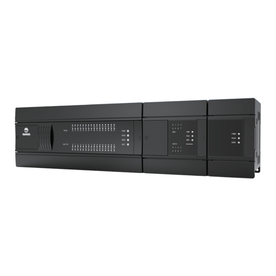
Page 4: Structure Description
Structure Description HC10 Series User Manual V1.5... - Page 5 Input and output terminal Battery Programming interface Run/Stop Input and output indicator Power/run/fault/battery indicator LED Mounting fixing hole (M3) DIN guideway groove (35mm) DIN rail fixing buckle Local expansion card installation location Expansion module interface HC10 Series User Manual V1.5...
- Page 6 RS485 MOD1+/MOD1-, MOD2+/MOD2- Power Power +24V (output) 24V, 0V +24V (output) 24V, 0V 200~240VAC L, N 200~240VAC L, N Size and Structure Size and Structure Size / structure Figure 1 Size / structure Figure 1 HC10 Series User Manual V1.5...
- Page 7 L, N High speed X0~X3 (S/S) Size and Structure Digital Output Size / structure Figure 2 Relay Y0~Y1 (COM0) , Y2~Y3 (COM1) Y4~Y7 (COM2) , Y10~Y13 (COM3) Transistor High speed Y0~Y1 (COM0) , Y2~Y3 (COM1) HC10 Series User Manual V1.5...
- Page 8 Power Relay Y0~Y1 (COM0) , Y2~Y3 (COM1) +24V (output) 24V, 0V Y4~Y7 (COM2) , Y10~Y13 (COM3) Transistor 200~240VAC L, N High speed Y0~Y1 (COM0) , Y2~Y3 (COM1) Size and Structure Size / structure Figure 2 HC10 Series User Manual V1.5...
- Page 9 X0~X7 (S/S) , X10~X17 (S/S) 200~240VAC L, N High speed X0~X3 (S/S) Size and Structure Digital Output Size / structure Figure 2 Relay Y0~Y1 (COM0) , Y2~Y3 (COM1) Y4~Y7 (COM2) Transistor High speed Y0~Y1 (COM0) , Y2~Y3 (COM1) HC10 Series User Manual V1.5...
- Page 10 CAN+/CAN- Digital Output Power Relay Y0~Y1 (COM0) , Y2~Y3 (COM1) +24V (output) 24V, 0V Y4~Y7 (COM2) Transistor 200~240VAC L, N High speed Y0~Y1 (COM0) , Y2~Y3 (COM1) Size and Structure Size / structure Figure 2 HC10 Series User Manual V1.5...
- Page 11 L, N High speed X0~X3 (S/S) Size and Structure Digital Output Size / structure Figure 2 Relay Y0~Y1 (COM0) , Y2~Y3 (COM1) Y4~Y7 (COM2) , Y10~Y17 (COM3) Transistor High speed Y0~Y1 (COM0) , Y2~Y3 (COM1) HC10 Series User Manual V1.5...
- Page 12 Power Relay Y0~Y1 (COM0) , Y2~Y3 (COM1) +24V (output) 24V, 0V Y4~Y7 (COM2) , Y10~Y17 (COM3) Transistor 200~240VAC L, N High speed Y0~Y1 (COM0) , Y2~Y3 (COM1) Size and Structure Size / structure Figure 2 HC10 Series User Manual V1.5...
- Page 13 X20~X21 (S/S) Size and Structure High speed X0~X3 (S/S) Size / structure Figure 2 Digital Output Relay Y0~Y1 (COM0) , Y2~Y3 (COM1) Y4~Y7 (COM2) , Y10~Y15 (COM3) Transistor High speed Y0~Y1 (COM0) , Y2~Y3 (COM1) HC10 Series User Manual V1.5...
- Page 14 High speed X0~X3 (S/S) Size and Structure Digital Output Size / structure Figure 3 Y0~Y1 (COM0) , Y2~Y3 (COM1) Relay Y4~Y7 (COM2) , Y10~Y17 (COM3) Transistor Y20~Y23 (COM4) High speed Y0~Y1 (COM0) , Y2~Y3 (COM1) HC10 Series User Manual V1.5...
- Page 15 X0~X3 (S/S) Size and Structure Digital Output Size / structure Figure 3 Y0~Y1 (COM0) , Y2~Y3 (COM1) Relay Y4~Y7 (COM2) , Y10~Y17 (COM3) Transistor Y20~Y27 (COM4) , Y30~Y37 (COM5) High speed Y0~Y1 (COM0) , Y2~Y3 (COM1) HC10 Series User Manual V1.5...
-
Page 16: Product Specifications
EFT: Power cable 2kV, I/O 1kV, Current compatibility OFF: <2.5mA (<5V) <1.2mA (<5V) analog 1kV Resistance 3.3kΩ 4.7kΩ Third grounding Hardware Ground (cannot be grounded in common About 200us filtering time with high voltage systems) Support pulse ≤100kHz ≤1kHz HC10 Series User Manual V1.5... - Page 17 ≤100kHz ≤1kHZ External voltage 5~30VDC 5~30VDC 250VAC, below 30VDC Resistive 50mA/1 point 50mA/1 point 3A/1 point (5A/COM) Max. load Inductive 1.2W (24VDC) 1.2W (24VDC) 80VA Light bulb 0.2W (24VDC) 0.2W (24VDC) 20W (DC) /100W (AC) HC10 Series User Manual V1.5...
- Page 18 5: VCC Resistance Voltage: 31kΩ 7: TXD+ (input) Current: 500Ω Voltage: 2kΩ~1MΩ Load (output) Current: 0~500Ω CAN interface CAN+, CAN- Voltage: 10mV Resolution Current: 10uA Array (input or 0~32000 output) Comprehensive ±3% full range accuracy HC10 Series User Manual V1.5...
- Page 19 DC24V output has short circuit protection 1. The power cable needs to be larger than 2mm to prevent voltage drop. 2. Avoid access to high-voltage, high-current power supplies or cables. 3. Do not overvoltage the power supply, polarity is correct. HC10 Series User Manual V1.5...
- Page 20 Instructions (Digital Input) Relay 24VDC 24VDC Relay Relay Drain Source Switching Switching power supply power supply Open-circuit Collect 24VDC 24VDC Drain NPN Source PNP 2-wire Proximity Switch 24VDC 24VDC Drain Source HC10 Series User Manual V1.5...
- Page 21 Load In order to prevent the load from short-circuiting and other blows to burn out the output unit, please select Fuse the fuse for each load. 5~10A +24V COM2 Load <AC 250V Relay Output relay HC10 Series User Manual V1.5...
- Page 22 • If the analog input or output is disturbed by noise, the 0.1~0.47uF 25V capacitor or ferrite ring can be connected. • Before current input or output, need to change the address corresponding to the analog to current type. HC10 Series User Manual V1.5...
- Page 24 Hpmont Group Company Hpmont (Malaysia) Sdn Bhd Shenzhen Hpmont Technology Co., Ltd. Add: VO3-11-20, Lingkaran SV, Sunway Velocity, 55100 Add: Building 28, Wangjingkeng Industry Park, Xili Town, Kuala Lumpur Nanshan District, Shenzhen, China Tel: +603 9202 8812 Tel: +86 755-26791688 Email: info.ma@hpmont.com.hk...
Need help?
Do you have a question about the HC10 Series and is the answer not in the manual?
Questions and answers