Table of Contents
Advertisement
Quick Links
Advertisement
Table of Contents

Related Manuals for hpmont HD5L series


Summary of Contents for hpmont HD5L series
- Page 2 Thank you for purchasing HD5L series elevator controller manufactured by Shenzhen Hpmont Technology Co., Ltd. This User Manual describes how to use HD5L series elevator controller and their installation wiring, parameter setting, troubleshooting and daily maintenance etc. Before using the product, please read through this User Manual carefully. In addition, please do not use this product until you have fully understood safety precautions.
- Page 3 Connection with peripheral devices Three-phase AC power supply MCCB Contactor AC input reactor EMI filter Braking resistor (optional) Controller DC reactor (optional) Ground connection EMI filter AC output reactor Motor Ground connection...
-
Page 4: Table Of Contents
CONTENTS Chapter 1 Safety Information and Precautions ................1 1.1 Safety Definition ....................... 1 1.2 About Motor and Load ...................... 1 1.3 Installation Limitation ......................2 Chapter 2 Product Information ...................... 3 2.1 Model Explanation ......................3 2.2 Nameplate ........................3 2.3 Specifications ........................ - Page 5 4.6.2 FD Description ....................28 4.6.3 DB15 Terminal ....................29 4.6.4 HD-PG2-OC-FD ....................29 4.6.5 HD-PG5-SINCOS-FD ..................32 4.6.6 HD-PG6-UVW-FD ....................34 4.6.7 HD-PG9-SC-FD ....................36 4.7 Meet EMC Requirement of Installation ................37 4.7.1 Correct EMC Installation ..................37 4.7.2 Wiring Requirement ...................
- Page 6 6.2.4 Group F03 Acceleration/Deceleration Parameters ..........63 6.2.5 Group F04 Analogue Curve Parameters ............64 6.2.6 Group F05 Speed Parameters ................65 6.2.7 Group F06 Weighing Compensation Parameters ..........67 6.2.8 Group F07 Asynchronous Motor Parameters............68 6.2.9 Group F08 Motor Vector Control Speed-loop Parameters ........71 6.2.10 Group F09 Current-loop Parameters ..............
- Page 7 Chapter 8 Troubleshooting ......................99 Chapter 9 Maintenance ......................103 9.1 Daily Maintenance ......................104 9.2 Periodical Maintenance ....................104 9.3 Replacing Damaged Parts .................... 105 9.4 Unwanted Controller Recycling ..................105 Chapter 10 Accessories ......................107 10.1 Panel Installation Assembly ..................107 10.1.1 Mounting Base ....................
- Page 8 Safety Information and Precautions Product Information Mechanical Installation Electrical Installation Operation Instructions Function Introduction Elevator Application Guidance Troubleshooting Maintenance Accessories Parameters Communication Protocol...
-
Page 10: Chapter 1 Safety Information And Precautions
1.2 About Motor and Load Compared to the standard frequency operation The HD5L series controllers are voltage-type controllers and their output is PWM wave with certain harmonic wave. Therefore, the temperature, noise and vibration of the motor will be a little higher than that at standard frequency operation. -
Page 11: Installation Limitation
Figure 1-1 is the derating curve of the controller rated current and the altitude. Controller’s rated current 100% Altitude(m) 1000 4000 Figure 1-1 Derating curve of controller rated current and altitude ―2― HD5L Series Controller User Manual... -
Page 12: Chapter 2 Product Information
Product model MODEL: HD5L-4T5P5 Adaptive motor POWER: 5.5kW Input specification INPUT: 3PH 380-460V 15A 50/60Hz Output specification OUTPUT: 8.5kVA 0-460V 13A 0-100Hz Software version Version: 1.00 Serial number Barcode S/N: Shenzhen Hpmont Technology Co., Ltd ―3― HD5L Series Controller User Manual... -
Page 13: Specifications
Motor temperature Real time detection for the motor temperature detection Power output grounding fault Power output grounding fault protection is enabled protection Power output short Power output short circuit protection is enabled circuit protection ―4― HD5L Series Controller User Manual... - Page 14 About panel 2 meter extension cable to panel (HD-CAB-2M) 3 meter extension cable to panel (HD-CAB-3M) 6 meter extension cable to panel (HD-CAB-6M) Enhanced protection Protective cover (HD-CK-Frame4) Power unit Power regenerative unit (HDRU) ―5― HD5L Series Controller User Manual...
-
Page 15: Ratings
24.1 HD5L-2S3P7 Three-phase power supply: 200-240V, 50/60Hz HD5L-2T3P7 HD5L-2T5P5 HD5L-2T7P5 HD5L-2T011 HD5L-2T015 HD5L-2T018 18.5 HD5L-2T022 HD5L-2T030 Three-phase power supply: 380-460V, 50/60Hz HD5L-4T2P2 HD5L-4T3P7 11.9 HD5L-4T5P5 HD5L-4T7P5 HD5L-4T011 HD5L-4T015 HD5L-4T018 18.5 HD5L-4T022 HD5L-4T030 HD5L-4T037 HD5L-4T045 ―6― HD5L Series Controller User Manual... -
Page 16: Parts Of Controller
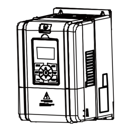
2.5 Parts of Controller Fan cover Mounting hole Mounting hole Middle enclosure Upper cover Bottom enclosure Display panel Certification Nameplate Lower cover Control terminal connection hole Power terminal connection hole Plastic structure Metal structure ―7― HD5L Series Controller User Manual... - Page 17 Chapter 2 Product Information Shenzhen Hpmont Technology Co., Ltd I/O card Refer to section 4.5 Control board Refer to section 4.4 Encoder card (optional) Refer to section4.6 L1 L2 L3 P1 (+) (-) MOTOR POWER ―8― HD5L Series Controller User Manual...
-
Page 18: Chapter 3 Mechanical Installation
2% for each degree centigrade. Max. allowed temperature is 50℃. 2. Keep ambient temperature between -10-+40℃. It can improve the controller operation performance if install at the location with good ventilation or cooling devices. ―9― HD5L Series Controller User Manual... -
Page 19: Installation Direction And Space Requirements
The requirements on mounting space and clearance are shown in Figure 3-1. ≥50 ≥30 ≥30 ≥50 Figure 3-1 Installation of the controller 3.4 Dimensions and Mounting Size 4-Ød Dimensions figure 1 ―10― HD5L Series Controller User Manual... - Page 20 Table 3-1 HD5L dimensions Dimensions (mm) Mounting size (mm) Gross weight Model Figure (kg) HD5L-2S2P2 HD5L-2S3P7 HD5L-2T3P7 HD5L-2T5P5 HD5L-4T2P2 HD5L-4T3P7 HD5L-4T5P5 HD5L-4T7P5 HD5L-4T011 HD5L-2T7P5 HD5L-4T015 HD5L-4T018 HD5L-2T011 HD5L-2T015 HD5L-2T018 20.4 HD5L-4T022 HD5L-4T030 HD5L-2T022 HD5L-2T030 HD5L-4T037 HD5L-4T045 ―11― HD5L Series Controller User Manual...
-
Page 21: Panel Installation And Dismantle
There are two steps in Figure 3-3. First, press the hook of the panel according to the direction 1. Second, take out of the panel according to the direction 2. STOP Figure 3-3 Dismantle of the panel ―12― HD5L Series Controller User Manual... -
Page 22: Plastic Cover Dismantle
Chapter 3 Mechanical Installation 3.6 Plastic Cover Dismantle The upper cover and the lower cover of the HD5L series controller are removable. The dismantle step is shown as Figure 3-4. Before removing the upper cover, please take away the panel. -
Page 24: Chapter 4 Electrical Installation
Do not connect the AC supply cable to the output terminals U/V/W of the controller. • Do not connect the phase-shifting capacitors to the output circuit. • The controller DC bus terminals must not be short-circuited. ―15― HD5L Series Controller User Manual... -
Page 25: Selection Of Main Circuit Peripheral Devices
Chapter 4 Electrical Installation Shenzhen Hpmont Technology Co., Ltd 4.2 Selection of Main Circuit Peripheral Devices Please refer to the Table 4-1 for the recommended specifications. Table 4-1 HD5L series controller I/O wiring specification Input Protection Main Circuit Control Circuit... -
Page 26: Terminals Description
Figure 4-2 HD5L power terminal connection During trial operation, make sure that the elevator will go up when the UP command is enabled. If the elevator goes down, set the parameter F00.08 (run direction) to be the reverse value. ―17― HD5L Series Controller User Manual... -
Page 27: Control Terminals And Wire Connection
Figure 4-3. Wire jumper Wire jumper Wire jumper CN9 CN5 and CN6 CN7 and CN8 SCI communication terminal Control terminal Figure 4-3 Positions of control terminal, wire jumper and SCI port in the control board ―18― HD5L Series Controller User Manual... -
Page 28: Control Terminal Description
200mA Factory settings default SEL and P24 are connected. Digital input common Disconnected SEL and P24 when use external power terminal to drive DI1-DI6 Digital reference Digital site, isolated from CME ground ―19― HD5L Series Controller User Manual... -
Page 29: Wire Jumper Description
When pin 1 and pin 2 of the CN9 are short-circuited, select the proper resistance. 4.4.3 SCI Communication Terminal Description Port pin Port signal 485+ 485- Reserved RJ45 Figure 4-5 SCI communication terminal and description ―20― HD5L Series Controller User Manual... -
Page 30: Control Terminal Connection
Multi-function input terminal 6 Digital ground Programmable relay output Shielded cable AI 1 AI 2 Analogue output channel 1 AI 3 Analogue ground Analogue output channel 2 Analogue ground Figure 4-6 HD5L control circuit connection diagram ―21― HD5L Series Controller User Manual... - Page 31 2. If the external power supply is used, the connection is as shown in Figure 4-8. (Note that the SEL and the P24 are not short-circuited) + 24V Dry contact connection using external power + 3.3V Current 12-30V DI1...DI6 Figure 4-8 Dry contact connection when using external power ―22― HD5L Series Controller User Manual...
- Page 32 2. If the external power supply is used, the drain connection is as shown in Figure 4-10. (Note that the SEL and the P24 are not short-circuited) + 24V DC 12-30V Drain connection using external power + 3.3V + 3.3V External controller Figure 4-10 Drain input connection when using external power ―23― HD5L Series Controller User Manual...
- Page 33 PNP transistor in the external controller is as shown in Figure 4-12. (Note that the SEL and the P24 are not short-circuited) + 24V PNP connection using internal power + 3.3V + 3.3V External controller Figure 4-12 PNP signal input connection when using internal 24V power supply ―24― HD5L Series Controller User Manual...
- Page 34 The connections are as shown in Figure 4-15. + 24V + 24V Relay coil Relay coil 12-30V Using the internal 24V power supply Using the external power supply Figure 4-15 DO terminal connection ―25― HD5L Series Controller User Manual...
-
Page 35: I/O Terminals And Wiring Connection
4.5 I/O Terminals and Wiring Connection HD5L series elevator controller has I/O card which can achieve the extension of analogue input, digital input and relay contact output. I/O card is shown as Figure 4-16 and the size unit is mm. -
Page 36: I/O Card Wire Jumper Description
Digital input terminal connection The digital input terminals (DI7-DI12) of I/O card and the digital input terminals (DI1-DI6) of control board have the same connection method. Please refer to 4.4.4 Control Terminal Connection for details. ―27― HD5L Series Controller User Manual... -
Page 37: Encoder Card
Shenzhen Hpmont Technology Co., Ltd 4.6 Encoder Card 4.6.1 Encoder Cards Introduction There are 4 kind encoder cards are provided for the HD5L series controller. And their models and functions are shown as Table 4-7. Table 4-7 Encoder card Encoder cards... -
Page 38: Db15 Terminal
Encoder B+ signal Power supply site, Encoder B- signal isolated from GND Encoder A+ signal OUTA FD output A signal, NPN type OCoutput Encoder A- signal OUTB FD output B signal, NPN type OCoutput ―29― HD5L Series Controller User Manual... - Page 39 Figure 4-23 Connection of differential output encoder +12V PG interface card + 5V HD-PG2-OC-FD Open-collector output encoder Interface circuit the same as A OUTA OUTB Elevator controller Figure 4-24 Connection of open-collector output encoder ―30― HD5L Series Controller User Manual...
- Page 40 The push-pull signal output encoder is shown as Figure 4-25. +12V PG interface card + 5V HD-PG2-OC-FD Push-pull output encoder Interface circuit the same as A OUTA OUTB Elevator controller Figure 4-25 Connection of push-pull output encoder ―31― HD5L Series Controller User Manual...
-
Page 41: Hd-Pg5-Sincos-Fd
Table 4-10 FD output terminal signal description Name Description OUTA FD output signal A, NPN type OC output OUTB FD output signal B, NPN type OC output FD output signal site, isolated from GND ―32― HD5L Series Controller User Manual... - Page 42 PG interface card PGVCC HD-PG5-SINCOS-FD SINCOS encoder Interface circuit the same as A Interface circuit the same as A Interface circuit the same as A OUTA OUTB Elevator controller Figure 4-27 Connection of SINCOS encoder ―33― HD5L Series Controller User Manual...
-
Page 43: Hd-Pg6-Uvw-Fd
Table 4-12 FD output terminal signal description Name Description OUTA FD output signal A, NPN type OC output OUTB FD output signal B, NPN type OC output FD output signal site, isolated from GND ―34― HD5L Series Controller User Manual... - Page 44 Interface circuit the same as A Interface circuit the same as A Interface circuit the same as A Interface circuit the same as A OUTA OUTB Elevator controller Figure 4-29 Connection of UVW encoder ―35― HD5L Series Controller User Manual...
-
Page 45: Hd-Pg9-Sc-Fd
CLK Differential signal C+/C- Signal D+/D- Data Data Differential signal D+/D- Terminal A+/A-/B+/B- Sin/Cos Signal Differential signal A+/A-/B+/B- FD description The FD coefficient of serial communication encoder card with FD output is set by F16.10. ―36― HD5L Series Controller User Manual... -
Page 46: Meet Emc Requirement Of Installation
IEC/61800-3 (VVVF drive system part 3: EMC specifications and test methods) are identical to the national standards GB/T12668.3. HD5L Series Controllers are designed and produced according to the requirements of IEC/61800-3. Please install the controller as per the description below so as to achieve good electromagnetic compatibility (EMC). -
Page 47: Wiring Requirement
When the cable between the motor and the controller is longer than 100 meters, it is recommended to install output reactor and adjust the carrier frequency as per the instruction in Table 4-14. ―38― HD5L Series Controller User Manual... -
Page 48: Ground Connections
The EMI filter should be used in the equipment that may generate strong EMI or the equipment that is sensitive to the external EMI. The EMI filter should be a dual-way low pass filter through which lower frequency current can flow while higher frequency current can hardly flow. ―39― HD5L Series Controller User Manual... -
Page 49: Conduction, Radiation And Radio Frequency Interference Countermeasures
The I/O cables and the controller produce radio frequency interference. A noise filter can be installed both on the input side and output side, and shield them with iron utensil to reduce RF interference. ―40― HD5L Series Controller User Manual... -
Page 50: Input And Output Reactor
Generally speaking, when the length of the cable between controller and motor is more than 100m, it will cause leakage current and controller tripping. It suggests that the user should consider installing an AC output reactor. ―41― HD5L Series Controller User Manual... -
Page 52: Chapter 5 Operation Instructions
Terminal speed control: The run command is controlled by UP and DN of the terminal; and the run speed is set by MS1-MS3 multi-step speed terminal combination. Communication speed control: The run command and the run multi-step speed are set by PC communication. ―43― HD5L Series Controller User Manual... -
Page 53: Control Mode
Chapter 5 Operation Instructions Shenzhen Hpmont Technology Co., Ltd 5.1.2 Control Mode HD5L series controllers have three control modes which respectively are V/f control, SVC control and VC control. (Refer to F00.01 for more detail) 5.1.3 Controller State HD5L series controller states respectively are: Stop, Run, Motor parameters auto-tuning, Fault alarm and Under-voltage. -
Page 54: Operating Instructions
Chapter 5 Operation Instructions 5.2 Operating Instructions 5.2.1 Panel Description The standard HD5L series controllers are installed with LCD panel which is shown as Figure 5-1. STOP Figure 5-1 Panel of HD5L controller There are keys on the panel and their functions, as shown in Table 5-1. -
Page 55: Display State
Chapter 5 Operation Instructions Shenzhen Hpmont Technology Co., Ltd 5.2.2 Display State The panel of HD5L series controller can display the parameters at stopping, running, editing and alarming. Note: STOP F03: 0.3 5 LCD anti-color displays: display in white on black such as etc. - Page 56 1 according to the according to the present Cycle according to when press this key present modified bit modified bit Y-F-D one time Switch units , ten Invalid Invalid Switch units and tens thousands, thousands, hundreds, tens ―47― HD5L Series Controller User Manual...
-
Page 57: Panel Operation Examples
Stop state Figure 5-6 Function parameter setting In the setting fourth-level menu situation, if the parameter is not in anti-color displaying, it indicates that this parameter can’t be modified. The possible reasons are as follows: ―48― HD5L Series Controller User Manual... - Page 58 STOP LO/RE STOP LO/RE STOP LO/RE Third-level menu Fourth-level menu Input correct password F01.01 Menu mode Unlock success 菜单模式 STOP LO/RE STOP LO/RE Third-level menu Unlock success Figure 5-8 Operation of unlocking user’s password ―49― HD5L Series Controller User Manual...
- Page 59 STOP LO/RE STOP LO/RE Third-level menu Third-level menu Fourth-level menu F01.01 Menu mode PW. has been cleared 菜单模式 菜单模式 STOP LO/RE STOP LO/RE Third-level menu Clear password Figure 5-10 Operation of clearing user’s password ―50― HD5L Series Controller User Manual...
- Page 60 Shenzhen Hpmont Technology Co., Ltd Chapter 5 Operation Instructions Panel self-testing The panel of the HD5L series controller has self-testing function which facilitates periodic inspection for itself and the keys. The process of panel self-testing: 1. In stopping state, press key and key simultaneously for 2-3 seconds, the panel will...
-
Page 61: Initial Power On
The panel will display as shown in Figure 5-14. Lu: Ready para. DC bus low Setting speed 请按键以检测其有效性 1.5 0 0 m/s Hpmont Technology STOP LO/RE STOP LO/RE Figure 5-14 Display initialing panel ―52― HD5L Series Controller User Manual... -
Page 62: Chapter 6 Function Introduction
Group F16 Enhance Function Parameters (on pages 81-82) Group F17 Fault Protect Parameters (on pages 82-85) Group F18 PWM Parameters (on pages 85-85) Group F19 Reserved Group F20 Reserved Manufacturer Function Parameters (on page 85) ―53― HD5L Series Controller User Manual... -
Page 63: Group D: Display Parameters
11: reserved 10: deceleration 1: at zero-speed 1: valid Bit3: DN Bit2: UP Bit1: run/stop Bit0: controller fault 0: no 0: no 0: stop 0: no fault 1: yes 1: yes 1: run 1: fault ―54― HD5L Series Controller User Manual... -
Page 64: Group D01 Drive State Parameters
Display the output torque which is the relative percentage of the motor rated torque. 【actual value】 D01.13 Output power Display the output power which is the relative percentage of the motor rated power. 【actual value】 D01.14 DC bus voltage Display the DC bus voltage. D01.15-D01.16 Reserved ―55― HD5L Series Controller User Manual... -
Page 65: Group D02 Analogue State Display Parameters
0V corresponds to 0mA, and 10.00V corresponds to 20mA. 【actual value】 D02.09 AO2 output Display AO2 output. When AO2 selects current output, the corresponding relations are: 0V corresponds to 0mA, and 10.00V corresponds to 20mA. ―56― HD5L Series Controller User Manual... -
Page 66: Group D03 Running State Parameters
D03.04 display total time at power-on; D03.05 displays total running time. The unit is hour. 【actual value】 D03.06 Running times Display the running times of the controller. 【actual value】 D03.07 Present fault Display the present fault. ―57― HD5L Series Controller User Manual... -
Page 67: Group D04 Encoder State Parameters
Displaying number of encoder pulses can be used to check the encoder is connected correctly. If the encoder is connected correctly, when the motor is rotated, D04.08 value is incremented or decremented in accordance with the running direction. D04.09-D04.11 Reserved ―58― HD5L Series Controller User Manual... -
Page 68: Group F: General Function Parameters
The formula for calculating motor mechanical parameters is as below: i × Winding mode D: Diameter of motor (mm); i: Dec. rate; Winding mode: The way that the hoist cable is wound, set according to the actual elevator setting. ―59― HD5L Series Controller User Manual... - Page 69 1: UP/DN switch. F00.07 Speed setting of panel 0.000-F00.02【1.500m/s】 When F00.05 = 0, it set the objective speed at running. F00.08 Run direction 0,1【0】 0: The same as run command. 1: Opposite to run command. ―60― HD5L Series Controller User Manual...
-
Page 70: Group F01 Protection Of Parameters
0: No operation. The controller is in regular parameter read/write state. 1: Parameter upload. Upload the present function code settings to the panel EEPROM parameter. Note: Group F01, F17.11-F17.27, Group F18 and Group Y do not upload. ―61― HD5L Series Controller User Manual... -
Page 71: Group F02 Start & Stop Parameters
It defines the time interval from controller’s zero-speed running to output brake-closed command. F02.06 Retention time of stop zero-speed 0.000-4.999【0.000s】 When stopping, the motor runs at zero-speed and has output torque during the retention time, which makes more comfortable. ―62― HD5L Series Controller User Manual... -
Page 72: Group F03 Acceleration/Deceleration Parameters
It defines the deceleration time of emergency stop. 】 F03.12 Abnormal Dec speed 0.020-9.999【1.000m/s It defines the deceleration time of emergency stop. 】 F03.13 Stop Dec jerk 0.020-9.999【0.350m/s It defines the deceleration time of emergency stop. ―63― HD5L Series Controller User Manual... -
Page 73: Group F04 Analogue Curve Parameters
Positive and negative characteristics of line Reference corresponding value Reference corresponding value F04.04 F04.02 F04.08 F04.06 Analogue Analogue F04.02 F04.04 (reference) (reference) F04.06 F04.08 F04.01 F04.03 F04.01 F04.03 F04.05 F04.07 F04.05 F04.07 ―64― HD5L Series Controller User Manual... -
Page 74: Group F05 Speed Parameters
(creeping speed) according to F03.12 (abnormal Dec speed). • Properly set this parameter to avoid climbing elevator at elevator up. F05.11 Down forced Dec detection value 0.0-100.0 (F00.02)【97.0%】 To avoid plunging elevator at elevator down. Refer to parameter F05.10. ―65― HD5L Series Controller User Manual... - Page 75 Set F05.19 or F05.20 as 0, the controller does not detect the excessive speed deviation fault of motor. F05.21 Reserved F05.22 Creeping speed 0.000-0.400【0.050m/s】 It defines the running speed at the forced Dec run. F05.23-F05.25 Reserved ―66― HD5L Series Controller User Manual...
-
Page 76: Group F06 Weighing Compensation Parameters
For example: If DI weighing signal 1 is enabled, it expresses that the present load is F06.08% of the rated load. • If numbers of terminals are enabled simultaneously, the max number terminal will be considered as the valid one. F06.12 Reserved ―67― HD5L Series Controller User Manual... -
Page 77: Group F07 Asynchronous Motor Parameters
F07.01 Asynchronous motor rated voltage 0V-Controller rated voltage 【Depend on controller model】 F07.02 Asynchronous motor rated current 0.0-999.9A 【Depend on controller model】 F07.03 Asynchronous motor rated frequency 1.00-100.00【50.00Hz】 F07.04 Asynchronous motor rated Rpm 1-24000【1440rpm】 ―68― HD5L Series Controller User Manual... - Page 78 Asynchronous motor excitation current 0.0-999.9A 【Depend on controller model】 F07.12 Asynchronous motor of core saturation coefficient 1 0.00-0.50【0.50】 F07.13 Asynchronous motor of core saturation coefficient 2 0.00-0.75【0.75】 F07.14 Asynchronous motor of core saturation coefficient 3 0.00-1.20【1.20】 ―69― HD5L Series Controller User Manual...
- Page 79 Asynchronous motor of oscillation-suppression coefficient 0-200【100】 This function is used to damp oscillation when output current is continually unstable. This function helps to keep the motor running smoothly through correctly adjusting the setting of F07.22. ―70― HD5L Series Controller User Manual...
-
Page 80: Group F08 Motor Vector Control Speed-Loop Parameters
There isn’t speed-loop differential when F08.07 = 0. F08.08 ASR output filter time 0.000-1.000【0.008s】 It is used to filter the output of ASR regulator. • When F08.08 = 0, the speed-loop filter is disabled. ―71― HD5L Series Controller User Manual... -
Page 81: Group F09 Current-Loop Parameters
【Depend on controller model】 F10.04 Synchronous motor rated frequency 1.00-100.00【19.20Hz】 F10.05 Synchronous motor rated rpm 1-24000【96rpm】 F10.06 Synchronous motor stator resistance 0.000-9.999【0.000Ω】 F10.07 Synchronous motor quadrature axis inductance 0.0-999.9【0.0mH】 F10.08 Synchronous motor direct axis inductance 0.0-999.9【0.0mH】 ―72― HD5L Series Controller User Manual... -
Page 82: Group F11
F11.05 specifies the duration time for detecting PG wire disconnection fault. The controller detects the PG wire disconnection and the duration time exceed F11.05, then the controller alarms E0031 fault (PG disconnection). • No detection will be conducted when F11.05 is set as 0. ―73― HD5L Series Controller User Manual... -
Page 83: Group F12 Digital I/O Terminal Parameters
• When no terminal selects this function, it defaults that the controller is at enabled state. 2,3: UP/DN. • You can set control terminal to control the controller’s up and down. UP Terminal DN Terminal Selection Stop Down Stop ―74― HD5L Series Controller User Manual... - Page 84 This parameter defines the MS in combination of filter time to make up for the time error of MS input terminals. • Change this parameter value according to the change asynchronous level of numbers of MS input terminals. F12.14 Reserved F12.15 DO1 terminal function 0-19【2】 F12.16 DO2 terminal function 0-19【3】 ―75― HD5L Series Controller User Manual...
- Page 85 Negative logic: When multi-function input terminals are connected to corresponding common port, this logic is disabled. Otherwise the logic is enabled. Bit5 Bit4 Bit3 Bit2 Bit1 Bit0 RLY4 RLY3 RLY2 RLY1 • 0 represents positive logic, while 1 represents negative logic. F12.22-F2.24 Reserved ―76― HD5L Series Controller User Manual...
-
Page 86: Group F13 Analogue I/O Terminal Parameters
That is, the smaller the constant, the shorter the response time, but the lower the immunity level. F13.16 AO1 terminal output function 0-9【0】 F13.17 AO2 terminal output function 0-9【0】 0: Disable. 1: Running speed (0-max output speed). 2: Setting speed (0-max output speed). ―77― HD5L Series Controller User Manual... - Page 87 The relationship between analogue output and gain is shown as following figure. Value after regulating (V) 100% F13.19=200% F13.19=100% Value before regulating (V) F13.20 AO2 bias -100.0-100.0【0.0%】 F13.21 AO2 gain 0.0-200.0【100.0%】 Refer to parameters F13.18 and F13.19. ―78― HD5L Series Controller User Manual...
-
Page 88: Group F14 Sci Communication Parameters
Run display parameter 2 set 0-32【6】 F15.04 Run display parameter 3 set 0-32【10】 F15.05 Run display parameter 4 set 0-32【11】 F15.06 Run display parameter 5 set 0-32【0】 F15.07 Run display parameter 6 set 0-32【0】 ―79― HD5L Series Controller User Manual... - Page 89 23: AO1 output. 24: AO2 output. 25: Heatsink temperature. 26: Input terminal state. 27: Output terminal state. 28: MODBUS state. 29: Total time at power on (hour). 30: Total running time (hour). 31, 32: Reserved. ―80― HD5L Series Controller User Manual...
-
Page 90: Group F16 Enhance Function Parameters
1: When detect that the motor is overheated, report E0020 (motor overheated) at once. F16.10 The coefficient of frequency demultiplication of 1-256【1】 HD-PG9-SC-FD To set the coefficient of frequency demultiplication of HD-PG9-SC-FD. F16.11-F16.24 Reserved ―81― HD5L Series Controller User Manual... -
Page 91: Group F17 Fault Protect Parameters
(F17.07). The factor can derive from the following Motor rated current ( F07.02 or F10.03 ) Motor overload protect factor ( F17.07 ) = × 100% formula: Controller rated output current ―82― HD5L Series Controller User Manual... - Page 92 • 1: Fault relay acts. Tens: During DC bus low • 0: Fault relay doesn’t act. • 1: Fault relay acts. Note: It need preset the relay function as No. 14 function. (Controller fault) ―83― HD5L Series Controller User Manual...
- Page 93 NO.5 fault interval F17.20 NO.4 fault type F17.21 NO.4 fault interval F17.22 NO.3 fault type F17.23 NO.3 fault interval F17.24 NO.2 fault type F17.25 NO.2 fault interval F17.26 NO.1 fault type F17.27 NO.1 fault interval ―84― HD5L Series Controller User Manual...
-
Page 94: Group F18 Pwm Parameters
0: Two phase / Three phase swtich. 1: Three phase. 6.2.20 Group F19 Reserved 6.2.21 Group F20 Reserved 6.3 Group Y Manufacturer Function Parameters The Group y is the manufacturer parameters group for debugging at the factory before delivery. ―85― HD5L Series Controller User Manual... -
Page 96: Chapter 7 Elevator Application Guidance
I/O terminal parameters of Group F13 according to the elevator actual requirement and the controller. The bigger Acc/Dec curve parameters of Group F03 are set, the quicker HD5L catch the speed command of elevator controller. ―87― HD5L Series Controller User Manual... -
Page 97: Motor Parameter Auto-Tuning
If the comparison value is too large, you could count it according to the following formula. And if the result is smaller than 5000, it means that the above steps are success too. Formula: 65535 + smaller value – larger value < 5000 ―88― HD5L Series Controller User Manual... - Page 98 When finishes auto-tuning, F10.14-F10.17 (encoder relevant parameters) and F10.12 (motor initial angle) will be obtained. Note: During step 2 and step 3, manually open the brake contactor and the run contactor together. ―89― HD5L Series Controller User Manual...
- Page 99 2. If the system has synchronous motor radial contactor, the short-circuit signal of radial contactor should be removed. Otherwise it will cause over-current fault. 3. If the system is power off before finish the step 7, you should restart auto-tuning. ―90― HD5L Series Controller User Manual...
- Page 100 2. There is fault such as over-current or encoder reversion enabled etc. It may be encoder reversion enabled. Take measures: Set F11.02 as 1 (the reverse direction of PG card), then restart auto-tuning. .123 ―91― HD5L Series Controller User Manual...
-
Page 101: Inspection Running
2. If the elevator has slight shake at running, please properly adjust Group F08. 3. To adjust leveling precision, terminal MS control (F00.05 = 2) can adjust Acc/Dec curve (Group F03) to unify level and adjust F03.13 (stop Dec jerk) to make leveling precision. ―92― HD5L Series Controller User Manual... -
Page 102: Terminal Ms Run Mode Application
Elevator MS terminal 2 controller MS terminal 3 Control board Controller fault RLY1 Controller running Zero-speed run sinA+,sinA- PG extension card cosB+,cosB- ERN1387 OUTA sinC+,sinC- DB15 OUTB cosD+,cosD- Figure 7-2 Terminal MS running connection ―93― HD5L Series Controller User Manual... -
Page 103: Set Parameter
UP regenerative torque limitation 180.0% default value. F08.12 DN regenerative torque limitation 180.0% F11.00 HD5L PG card Depend on actual value F11.01 PG P/R Depend on actual value F11.02 PG direction setting Depend on actual value ―94― HD5L Series Controller User Manual... - Page 104 DI5 terminal function F12.06 DI6 terminal function F12.15 DO1 terminal function Controller is running Controller is at zero-speed F12.16 DO2 terminal function running F12.17 RLY1 terminal function Controller fault F16.07 Multi-sped inspection select Multi-speed inspection select ―95― HD5L Series Controller User Manual...
-
Page 105: Terminal Analogue Run Mode Application
Controller enable Up (UP) Down (DN) Controller fault HD5L RLY1 Elevator Running controller Control board Zero-speed run Weighing signal Speed command PG extension card PG feedback signal OUTA OUTB Figure 7-3 Terminal analogue running connection ―96― HD5L Series Controller User Manual... -
Page 106: Set Parameter
AI2 function Weighing signal F13.04 AI1 bias 0.0% F13.05 AI1 gain 1.00 F13.06 AI1 filter time 0.05s Adjust according to actual situation F13.07 AI2 bias 0.0% F13.08 AI2 gain 1.00 F13.09 AI2 filter time 0.05s ―97― HD5L Series Controller User Manual... -
Page 107: Power-Off Battery Driven Run Mode Application
Note: 1. The battery voltage should be bigger than 240VDC to ensure normal operation. 2. In the battery driven running mode, the controller does not detect the input phase failure. ―98― HD5L Series Controller User Manual... -
Page 108: Chapter 8 Troubleshooting
Controller external ventilation is • Improve the ventilation around Heatsink not good E0009 the controller overheated • Fan fault • Replace the cooling fan • Fault occurs to temperature • Please seek technical support detection circuit ―99― HD5L Series Controller User Manual... - Page 109 • Detect the overheat detection E0020 Motor overheat incorrect connection input signal whether correct • The setting of motor • Set the motor parameter paramteters is incorrect according to the motor’s nameplates ―100― HD5L Series Controller User Manual...
- Page 110 PG disconnection • Check the PG connection encoder • Contactor damage • Change the contactor E0036 Contator faulty • Feedback contact connection • Check the connection problem Mark: E0022 doesn’t affect the controller normal operation. ―101― HD5L Series Controller User Manual...
-
Page 112: Chapter 9 Maintenance
Do not make modification on the inside of controller without instruction from the supplier. • There are IC components inside the controller, which are sensitive to static electricity. Directly touch the components on the PCB board is forbidden. ―103― HD5L Series Controller User Manual... -
Page 113: Daily Maintenance
3. For controllers that have been stored for a long time, they must be powered up every 2 years. When supplying AC power to the controller, use a voltage regulator to gradually raise the input voltage to rated input voltage at least 5 hours. ―104― HD5L Series Controller User Manual... -
Page 114: Replacing Damaged Parts
When disposing the controller, please pay attention to the following factors: The capacitors may explode if they are burnt. Poisonous gas may be generated when the plastic parts like front covers are burnt. Disposing method: Please dispose unwanted controllers as industrial waste. ―105― HD5L Series Controller User Manual... -
Page 116: Chapter 10 Accessories
The panel extension cable is an accessory. If needed, please order goods. The models are as follows: • 1m extension cable to panel: HD-CAB-1M • 2m extension cable to panel: HD-CAB-2M • 3m extension cable to panel: HD-CAB-3M • 6m extension cable to panel: HD-CAB-6M ―107― HD5L Series Controller User Manual... -
Page 117: Braking Resistor Selection
Model: HD-CK-Frame4. The protective cover is applied to plastic structure controller (18.5kW and below model), and each controller needs 2 protective covers. 10.4 Power Regenerative Unit Please refer to HDRU Series Power Regenerative Unit User Manual for more details. ―108― HD5L Series Controller User Manual... -
Page 118: Appendix A Parameters
“×”: It denotes that the setting parameter cannot be modified when the controller is in run state. ”○”: It denotes that the setting parameter can be modified when the controller is in run state. -109- HD5L Series Controller User Manual... - Page 119 D01.01 Setting speed(m/s) 0.000-9.999 Actual value Setting speed (after D01.02 0.000-9.999 Actual value acc/dec)(m/s) D01.03 Feedback speed(m/s) 0.000-9.999 Actual value D01.04 Setting frequency (Hz) 0.01-100.00Hz Actual value D01.05 0.01-100.00Hz Actual value Setting frequency (after ―110― HD5L Series Controller User Manual...
- Page 120 Actual value DI12-DI1 0: Connected 1: Unconnected Display in 16-bit binary, from high to low bit is as follows: Bit15-Bit6: reserved D03.02 Output terminal state Actual value Bit5-Bit2 corresponds to RLY4-RLY1 Bit1-Bit0 corresponds to DO2-DO1 -111- HD5L Series Controller User Manual...
- Page 121 5.00-100.00Hz 50.00Hz 0.01Hz freqency Traction machine × F00.04 10.0-6000.0 60.0 mechanical parameters 0: Panel control 1: Terminal analogue control 2: Terminal MS control × F00.05 Operating mode 3: Reserved 4: SCI control 5: Reserved ―112― HD5L Series Controller User Manual...
- Page 122 Group F03 Acceleration/Deceleration Parameters (on pages 63-64) 0.001 × F03.00 Acceleration speed 0.020-9.999m/s 0.700m/s 0.001 × F03.01 Start Acc jerk 0.020-9.999m/s 0.350m/s 0.001 × F03.02 End Acc jerk 0.020-9.999m/s 0.600m/s × F03.03 Deceleration speed 0.020-9.999m/s 0.700m/s 0.001 -113- HD5L Series Controller User Manual...
- Page 123 Reference curve 0000 Thousands: AI4 characteristic curve 0: Line 1 1: Line 2 Line 1 minimum ○ F04.01 0.0-F04.03% 0.0% 0.1% reference Corresponding value of ○ F04.02 line 1 minimum 0.0-100.0% 0.0% 0.1% reference ―114― HD5L Series Controller User Manual...
- Page 124 FDT2 0.0-100.0%(F00.02) 90.0% 0.1% ○ F05.14 FDT1 delay level 0.0-100.0%(F00.02) 1.0% 0.1% ○ F05.15 FDT2 delay level 0.0-100.0%(F00.02) 1.0% 0.1% ○ F05.16 FAR range 0.0-20.0%(F00.02) 1.0% 0.1% × F05.17 Over-speed setting 80.0-120.0%(F00.02) 115.0% 0.1% -115- HD5L Series Controller User Manual...
- Page 125 No weighing speed-loop ○ F06.15 1-9999 2000 No weighing speed-loop ○ F06.16 1-9999 2000 F06.17-F06.20 Reserved Group F07 Asynchronous Motor Parameters (on pages 68-71) Asynchronous motor Depend on × F07.00 0.2-400.0kW 0.1kW rated power controller ―116― HD5L Series Controller User Manual...
- Page 126 Asynchronous motor of ○ F07.18 slip compensation filter 0.1-10.0s 0.1s 0.1s time Asynchronous motor of × F07.19 slip compensation 0.0-250.0% 200.0% 0.1% limitation 0: No action ○ F07.20 AVR function 1: Action all the time -117- HD5L Series Controller User Manual...
- Page 127 1-4000 0.000-1.000s Current-loop output filter ○ F09.02 0.000s 0.001s 0.000: current-loop output time without filter F09.03-F09.07 Reserved Group F10 Synchronous Motor Parameters (on pages 72-73) 0: IPM × F10.00 Synchronous motor type 1: SPM ―118― HD5L Series Controller User Manual...
- Page 128 × F10.17 SINCOS encoder D 0-9999 2048 zero-bias F10.18-F10.20 Reserved Group F11 PG Parameters (on pages 73-74) 1: HD-PG2-OC-FD is valid 2: HD-PG6-UVW-FD is valid × F11.00 HD5L PG card 3: HD-PG5-SINCOS-FD is valid -119- HD5L Series Controller User Manual...
- Page 129 × F12.11 DI11 terminal function (OH) 16: Fault reset input (RST) 17: Up forced Dec input (UPF) 18: Down forced Dec input × F12.12 DI12 terminal function (DNF) 19-33: Reserved 34: External fault (EXT) ―120― HD5L Series Controller User Manual...
- Page 130 AI4 function input (only AI4) ○ F13.04 AI1 bias -100.0-100.0% 0.0% 0.1% ○ F13.05 AI1 gain -10.00-10.00 1.00 0.01 ○ F13.06 AI1 filter time 0.01-10.00s 0.05s 0.01s ○ F13.07 AI2 bias -100.0-100.0% 0.0% 0.1% -121- HD5L Series Controller User Manual...
- Page 131 Data format 3: 1-7-2 format, no parity, ASCII 4: 1-7-1 format, even parity, ASCII 5: 1-7-1 format, odd parity, ASCII 0: 1200bps 1: 2400bps × F14.01 Baud rate selection 2: 4800bps 3: 9600bps 4: 19200bps ―122― HD5L Series Controller User Manual...
- Page 132 F15.11 4 set 22: AI4 voltage(After disposal) Stop display parameter ○ F15.12 23: AO1 output 5 set 24: AO2 output 25: Heatsink temperature Stop display parameter ○ F15.13 6 set 26: Input terminal state -123- HD5L Series Controller User Manual...
- Page 133 Threshold resistance at × F17.02 0.0-10.0kΩ 5.0kΩ 1.0kΩ motor overheated The detect base of lack 0-100%(controller rated × F17.03 of input voltage) The detect time of lack × F17.04 0.0-5.0s 1.0s 1.0s of input ―124― HD5L Series Controller User Manual...
- Page 134 E0014: Current detect faulty E0015: Lack of input E0016: Lack of output E0017: Controller overloaded E0018: Excessive speed deviation E0019: Motor overloaded E0020: Motr overheated E0021: Controlborad EEPROM faulty E0022: Panel EEPROM faulty E0023: Parameter setting faulty -125- HD5L Series Controller User Manual...
- Page 135 NO.1 fault type 0-36 F17.27 NO.1 fault interval 0.0-6553.5 hour 0.0h 0.1h Group F18 PWM Parameters (on pages 85-85) Depend on × F18.00 Carrier fregency 1-16kHz controller 1kHz model × F18.01 0: Disable Carrier freqency auto ―126― HD5L Series Controller User Manual...
- Page 136 Name Range Default Unit Attributes Setting adjust enable 1: Enable 0: Disable PWM overmodulation × F18.02 enable 1: Enable 0: Two phase / Three phase PWM overmodulation × swtich F18.03 mode 1: Three phase -127- HD5L Series Controller User Manual...
-
Page 138: Appendix B Communication Protocol
Appendix B Communication Protocol 1. Peripherals Support HD5L series controllers provide one RS485 communication interface which uses the standard MODBUS communication protocol. By using the host computer (including communication devices such as computer and PLC) the user can operate to read-write the controller’s function code, read the state parameters and write the control command etc. - Page 139 Except the parameters of the remarks, all other function codes can define the scaling relationship of the specified function code via referring the manual’s minimum unit. Remarks: Communication data 0-2000 of F06.07, F13.04, F13.05, F13.07, F13.08, F13.10, F13.11, F13.18 and F13.20 corresponds to data -1000 - +1000. ―130― HD5L Series Controller User Manual...
- Page 140 The register number of command frame is fault. Incorrect information frame, including incorrect information length and incorrect 0x18 checking. 0x20 Parameters cannot be modified. 0x21 Parameters are unchangeable when the controller is in running state. 0x22 Parameters are protected by password. -131- HD5L Series Controller User Manual...
- Page 141 0-247, 0 is broadcast Address address Function code 0x08 Command frame Subfunction code 0x0000-0x0030 Data 0x0000-0xFFFF CRC /LRC checking Address 1-247 Function code 0x08 Response frame Subfunction code 0x0000-0x0030 Data 0x0000-0xFFFF CRC /LRC checking ―132― HD5L Series Controller User Manual...
- Page 142 0-247, 0 is broadcast Address address Function code 0x41 Command frame Register address 0x0000-0xFFFF Register content 0x0000-0xFFFF CRC /LRC checking Address 1-247 Function code 0x41 Response frame Register address 0x0000-0xFFFF Register content 0x0000-0xFFFF CRC /LRC checking -133- HD5L Series Controller User Manual...
- Page 143 0-247, 0 is broadcast address Function code 0x42 Command frame Subfunction code 0x0000-0x0008 Data Depend on controller model CRC /LRC checking Address 1-247 Function code 0x42 Response frame Subfunction code 0x0000-0x0008 Data 0x0000-0xFFFF CRC /LRC checking ―134― HD5L Series Controller User Manual...
- Page 144 Value Definition To modify the upper limit as per character restriction Bit0 To modify the upper limit as per 4-byte restriction without decimal fraction 1 decimal fraction Bit2-Bit1 2 decimal fraction 3 decimal fraction -135- HD5L Series Controller User Manual...
- Page 145 10100B Unit is s/times 10101B Unit is m/s 10110B Unit is m/s 10111B Unit is m/s 11000B Unit is mm 11001B Unit is m/min 11010B Unit is kg/m 11011B Unit is N Others reserved ―136― HD5L Series Controller User Manual...
- Page 146 Register address Parameter name Retained or not at power loss 0x3200 Control command character 0x3201 Main setting Definition of controller control command words: Note: The controller operating mode must be SCI control (F00.05 = 4). -137- HD5L Series Controller User Manual...
- Page 147 Speed corresponding to parameter F05.01 Speed corresponding to parameter F05.02 Speed corresponding to parameter F05.03 Speed corresponding to parameter F05.04 Speed corresponding to parameter F05.05 Speed corresponding to parameter F05.06 Speed corresponding to parameter F05.07 Reserved ―138― HD5L Series Controller User Manual...
- Page 148 3. If many multi-function input terminals setting are the same, it may cause dysfunction. Therefore, the user should avoid this case when modify the multi-function terminal function via the MODBUS. -139- HD5L Series Controller User Manual...
- Page 149 =crcvalue[uIndex]&0xff; return (uchCRCHi | uchCRCLo<<8) ; /* Table of CRC values */ const unsigned int crcvalue[ ] = { 0x0000,0xC1C0,0x81C1,0x4001,0x01C3,0xC003,0x8002,0x41C2,0x01C6,0xC006,0x8007, 0x41C7,0x0005,0xC1C5,0x81C4,0x4004,0x01CC,0xC00C,0x800D,0x41CD,0x000F,0xC1CF, 0x81CE,0x400E,0x000A,0xC1CA,0x81CB,0x400B,0x01C9,0xC009,0x8008,0x41C8,0x01D8, 0xC018,0x8019,0x41D9,0x001B,0xC1DB,0x81DA,0x401A,0x001E,0xC1DE,0x81DF,0x401F, 0x01DD,0xC01D,0x801C,0x41DC,0x0014,0xC1D4,0x81D5,0x4015,0x01D7,0xC017,0x8016, 0x41D6,0x01D2,0xC012,0x8013,0x41D3,0x0011,0xC1D1,0x81D0,0x4010,0x01F0,0xC030, 0x8031,0x41F1,0x0033,0xC1F3,0x81F2,0x4032,0x0036,0xC1F6,0x81F7,0x4037,0x01F5, 0xC035,0x8034,0x41F4,0x003C,0xC1FC,0x81FD,0x403D,0x01FF,0xC03F,0x803E,0x41FE, 0x01FA,0xC03A,0x803B,0x41FB,0x0039,0xC1F9,0x81F8,0x4038,0x0028,0xC1E8,0x81E9, 0x4029,0x01EB,0xC02B,0x802A,0x41EA,0x01EE,0xC02E,0x802F,0x41EF,0x002D,0xC1ED, 0x81EC,0x402C,0x01E4,0xC024,0x8025,0x41E5,0x0027,0xC1E7,0x81E6,0x4026,0x0022, 0xC1E2,0x81E3,0x4023,0x01E1,0xC021,0x8020,0x41E0,0x01A0,0xC060,0x8061,0x41A1, 0x0063,0xC1A3,0x81A2,0x4062,0x0066,0xC1A6,0x81A7,0x4067,0x01A5,0xC065,0x8064, 0x41A4,0x006C,0xC1AC,0x81AD,0x406D,0x01AF,0xC06F,0x806E,0x41AE,0x01AA,0xC06A, 0x806B,0x41AB,0x0069,0xC1A9,0x81A8,0x4068,0x0078,0xC1B8,0x81B9,0x4079,0x01BB, ―140― HD5L Series Controller User Manual...
- Page 150 Code Register address Word no. of read Checksum 0x02 0x03 0x00 0x06 0x00 0x01 0x64 0x38 Corresponding answer frame (F00.06=1): Address Code Answer byte Register content Checksum 0x02 0x03 0x02 0x00 0x01 0X3D 0x84 -141- HD5L Series Controller User Manual...
- Page 151 No. 0x02 0x43 0x32 0x00 0x00 0x02 0x04 0x00 0x1F 0x00 0x02 0xF2 0xC3 Corresponding answer frame: Address Code Register address Register content Checksum 0x02 0x43 0x32 0x00 0x00 0x02 0xCB 0x4F ―142― HD5L Series Controller User Manual...
- Page 152 9. Battery driven up run of address 2. Address Code Register address Register content Checksum 0x02 0x41 0x32 0x00 0x20 0x0D 0xEB 0x4B Corresponding answer frame: Address Code Register address Register content Checksum 0x02 0x41 0x32 0x00 0x20 0x0D 0xEB 0x4B -143- HD5L Series Controller User Manual...
- Page 154 Shenzhen Hpmont Technology Co., Ltd Product Warranty Card Unit: Add. Of unit: P.C.: Contact person: Tel.: Fax: Barcode on the product body (paste here): Power: Model: Contrat number: Purchasing date: Service unit: Contact person: Tel.: Maintenance staff: Tel.: Maintenance date: User’s quality evaluation for the service:...
- Page 155 7. If there is any problem during the service, please contact the agent of our company or our company directly. 8. This agreement should be interpreted by Shenzhen Hpmont Technology Co., Ltd. Shenzhen Hpmont Technology Co., Ltd Address: 3F, Building 28, Wangjingkeng Industry Park, Xili Dakan,...
Need help?
Do you have a question about the HD5L series and is the answer not in the manual?
Questions and answers