Table of Contents
Advertisement
Advertisement
Chapters
Table of Contents

Related Manuals for hpmont HD5L Series


Summary of Contents for hpmont HD5L Series
- Page 1 HD5L Series Elevator Controller User Manual V1.4 2017.05...
- Page 2 Thank you for purchasing HD5L series elevator controller manufactured by Shenzhen Hpmont Technology Co., Ltd. This User Manual describes how to use HD5L series elevator controller and their installation wiring, parameter setting, troubleshooting and daily maintenance etc. Before using the product, please read through this User Manual carefully. In addition, please do not use this product until you have fully understood safety precautions.
- Page 3 Connection with peripheral devices Three-phase AC power supply MCCB Contactor AC input reactor (accessory) EMI filter Braking resistor (accessory) HD5L DC reactor (accessory) EMI filter AC output reactor (accessory) Motor...
- Page 4 Version and Revision Records The version information is on top of the backbone and the bottom left of the cover. Time: 2017/05 Version: V1.4 Revised chapter Revised contents • HD-PG9-SC-FD replaced by encoder card HD-PG11-SC-FD, see 4.5.7 Chapter four • F02.05 (brake relase delay time) default value changed: [0.200s] Chapter six •...
-
Page 6: Table Of Contents
CONTENTS Chapter 1 Safety Information and Precautions ....................1 1.1 Safety Definition ..........................1 1.2 About Motor and Load ........................1 1.3 About HD5L ............................2 Chapter 2 Product Information ..........................5 2.1 Model ..............................5 ... - Page 7 4.5.4 HD-PG2-OC-FD ............................27 4.5.5 HD-PG5-SINCOS-FD ........................... 29 4.5.6 HD-PG6-UVW-FD ............................30 4.5.7 HD-PG11-SC-FD ............................32 4.6 Meet EMC Requirement of Installation ..................33 4.6.1 Correct EMC Installation .......................... 33 4.6.2 Wiring Requirement ..........................34 ...
- Page 8 6.2.7 F06: Weighing Compensation Parameters ..................59 6.2.8 F07: Asyn. motor Parameters ......................... 60 6.2.9 F08: Motor Vector Control Speed-loop Parameters ............... 63 6.2.10 F09: Current-loop Parameters ......................64 6.2.11 F10: Syn. motor Parameters ......................... 65 ...
- Page 10 Safety Information and Precaution Product Information Mechanical Installation Electrical Installation Operation Instructions Function Introduction Elevator Application Guidance Troubleshooting and Maintenance Accessories Parameters Communication Protocol...
-
Page 12: Chapter 1 Safety Information And Precautions
1.2 About Motor and Load Compared to the industrial frequency operation The HD5L series controllers are voltage-type controllers and their output is PWM wave with certain harmonic wave. Therefore, the temperature, noise and vibration of the motor will be a little higher than that at industrial frequency running. -
Page 13: About Hd5L
36V. Generally, the internal circuit enables the capacitor to discharge. However, the discharging may fail in some exceptions. In these cases, users need to consult Hpmont or our regional distributor. Change three-phase input to single-phase input For three-phase input controller, users should not change it to be single-phase input. - Page 14 3000m, derated rate is 20% for rated current of HD5L. Figure 1-1 is the derating curve of rated current and the altitude. Rated current of HD5L 100% Altitude 1000m 4000m Figure 1-1 Derating curve of rated current and altitude ―3― HD5L Series Controller User Manual V1.4...
-
Page 16: Chapter 2 Product Information
Serial communication encoder interface board with FD output = PG11 Special Feature 2.2 Nameplate MODEL: HD5L-4T5P5G Product model 5.5kW Motor power POWER: INPUT: Input specification 3PH 380-460V 15A 50/60Hz OUTPUT: 8.5kVA 0-460V 13A 0-100Hz Output specification Version: 1.00 Software version Serial number ―5― HD5L Series Controller User Manual V1.4... -
Page 17: Technical Data
Input / Output phase loss Input / Output phase loss auto-detect and alarm function protection Motor temperature Real time detection for the motor temperature detection Output GND short circuit Enabled protection Output inter-phase short Enabled circuit protection ―6― HD5L Series Controller User Manual V1.4... - Page 18 Line drive encoder interface board with FD output [HD-PG6-UVW-FD] frequency demultiplication Serial communication encoder interface board with FD output [HD-PG11-SC-FD] (support Endat) Mounting base to keypad [HD-KMB] About keypad 1m/2m/3m/6m extension cable to keypad [HD-CAB-1M/2M/3M/6M] Power unit Power regenerative unit [HDRU] ―7― HD5L Series Controller User Manual V1.4...
-
Page 19: Rated Value
Three-phase power supply: 380 - 460V, 50/60Hz HD5L-4T2P2 HD5L-4T3P7 11.9 HD5L-4T5P5 HD5L-4T7P5 HD5L-4T011 HD5L-4T015 HD5L-4T018 18.5 HD5L-4T022 HD5L-4T030 HD5L-4T037 HD5L-4T045 (1): Value before / is for single-phase model, value after / is for three-phase model. ―8― HD5L Series Controller User Manual V1.4... -
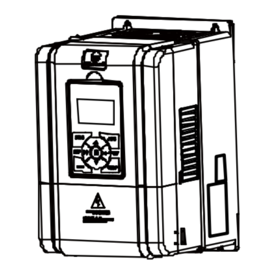
Page 20: Parts Of Controller
Refer to section 4.4 Control board Refer to section 4.4 Encoder interface board Optional, refer to section 4.5 Supply and motor terminal Refer to section 4.3 L1 L2 L3 P1 (+) (-) MOTOR POWER ―9― HD5L Series Controller User Manual V1.4... -
Page 22: Chapter 3 Mechanical Installation
2% for each degree centigrade. Max. allowed temperature is 50 ℃ 2. Keep ambient temperature between -10 - +40 . It can improve the running performance if install at location with good ventilation or cooling devices. ―11― HD5L Series Controller User Manual V1.4... -
Page 23: Installation Direction And Space Requirements
The dimensions and weight of HD5L are as shown in figure Table 3-1. For the corresponding model of the mounting size, please refer to section 2.4 Rated Value, on page 8. 4-Ød Size F3 - F4 4-Ød Size F5 - F6 ―12― HD5L Series Controller User Manual V1.4... -
Page 24: Install And Dismantle Keypad
There are two steps in Figure 3-3. First, press the hook of the keypad according to direction 1. Second, take out of the keypad according to direction 2. STOP Figure 3-3 Dismantle keypad ―13― HD5L Series Controller User Manual V1.4... -
Page 25: Dismantle Plastic Cover
(a). 2. Dismantle the screws of upper cover, as (b). 3. Extrude the hooks at both sides together, take off the upper cover, as (c). Figure 3-4 Dismantle plastic cover ―14― HD5L Series Controller User Manual V1.4... -
Page 26: Chapter 4 Electrical Installation
Sectional area S of phase conductor (power supply S ≤ 2.5 2.5 < S ≤ 16 16 < S ≤ 35 S > 35 cable) while installing (mm Min. sectional area Sp of relative protective conductor (ground cable) (mm ―15― HD5L Series Controller User Manual V1.4... -
Page 27: Power Terminal Lug
Table 4-3 Selection of power terminal lug Size F3 / F4 Screw size Tightening torque (N. M) 2.5 - 3.0 4.0 - 5.0 9.0 - 10.0 Max. outer diameter of 15.5 lug d (mm) ―16― HD5L Series Controller User Manual V1.4... -
Page 28: Main Circuit
Output terminals, connect to three-phase AC motor P1, (+) DC reactor connection terminals (+), (-) DC supply input terminals; DC input terminals of power regenerative unit (+), BR Braking resistor connection terminals Ground terminal, connect to the ground ―17― HD5L Series Controller User Manual V1.4... -
Page 29: Supply And Motor Connection
• If connect the communication terminal of the control circuit to the PC, choose the RS485/232 isolating converter which meets the safety requirement. • Only connect the relay terminal to AC 220V voltage signal. Other control terminals are strictly forbiden for this connection. ―18― HD5L Series Controller User Manual V1.4... -
Page 30: Control Board Terminal
Programmable output, contact rating: 250VAC/3A or 30VDC/1A R1A/ R1B/ R1C Relay output • R1B,R1C: normally closed; R1A,R1C: normally open Note: Limit the current within 3A if the relay terminal is to connect to AC 220V voltage signal. ―19― HD5L Series Controller User Manual V1.4... -
Page 31: I/O Board Terminal
• RB,RC: normally closed; RA,RC: normally open R4A/R4B/R4C Note: Limit the current within 3A if the relay terminal is to connect to AC 220V voltage signal. 4.4.3 Modbus Communication Terminal Difinition RJ45 Control Board 485+ RJ45 4,5,6 485- Unused ―20― HD5L Series Controller User Manual V1.4... -
Page 32: Jumper
• Pin 1 & 2 are short- connected, AI4 is for the user reference analogue input (factory I/O board setting). • Pin 2 & 3 are short- connected, AI4 is for the motor over-heating detection signal input via the external connected thermistor. ―21― HD5L Series Controller User Manual V1.4... -
Page 33: Control Terminal Wiring
(remove the connector between SEL and P24), their connections are shown in Figure 4-7. +24V +24V Dry contact Dry contact Using internal Using external Current 12 - 30V power supply Current power supply DI1...DI12 DI1...DI12 Figure 4-7 Dry contact connection ―22― HD5L Series Controller User Manual V1.4... - Page 34 Figure 4-9. (For PNP, remove the connector between SEL and P24) +24V +24V Using internal Using internal power supply power supply DI12 DI12 Figure 4-9 NPN (source) / PNP (drain) connection when using internal power supply ―23― HD5L Series Controller User Manual V1.4...
- Page 35 When AI4 is used as setting analogue input terminal, the connection is shown as Figure 4–12. (The AI4+ = analogue signal input) Analogue input AI4+ -10 - +10V/0 - 20mA AI4- Figure 4–12 AI4 connection (AI4 = analogue input terminal) ―24― HD5L Series Controller User Manual V1.4...
- Page 36 DO1 can use internal 24V power supply of HD5L or external power supply, the connection is shown in Figure 4–14. DO1 connection also applies to DO2. +24V +24V Relay coil 12 - 30V Figure 4–14 DO1 connection ―25― HD5L Series Controller User Manual V1.4...
-
Page 37: Encoder Interface Board
Shenzhen Hpmont Technology Co., Ltd. 4.5 Encoder Interface Board 4.5.1 Encoder Interface Board Introduction There are 4 kind encoder interface boards provided for HD5L series controller. And their models and functions are shown as Table 4-8. Table 4-8 Encoder interface boards... -
Page 38: Hd-Pg2-Oc-Fd
B+ / B- signals of encoder Connection HD-PG2-OC-FD +12V + 5V Differential output encoder Interface circuit the same as A OUTA OUTB OUTA OUTB Elevator controller Figure 4-17 Connection of differential output encoder ―27― HD5L Series Controller User Manual V1.4... - Page 39 Figure 4-18 Connection of open-collector output encoder HD-PG2-OC-FD +12V + 5V Push-pull output encoder Interface circuit the same as A OUTA OUTB OUTA OUTB Elevator controller Figure 4-19 Connection of push-pull output encoder ―28― HD5L Series Controller User Manual V1.4...
-
Page 40: Hd-Pg5-Sincos-Fd
Output A signal, NPN type OC output PGVCC +5V power supply OUTB Output B signal, NPN type OC output Differential signal C+ / C- 10 / 11 C+ / C- Output ground, isolated from GND ―29― HD5L Series Controller User Manual V1.4... -
Page 41: Hd-Pg6-Uvw-Fd
Figure 4-21 Connection of SINCOS encoder 4.5.6 HD-PG6-UVW-FD HD-PG6-UVW-FD high bit FD switch low bit DB15 FD output OUTA terminal OUTB Figure 4-22 4.5.5 HD-PG6-UVW-FD FD Switch FD switch is shown as section 4.5.3 FD Description. ―30― HD5L Series Controller User Manual V1.4... - Page 42 A Interface circuit the same as A Interface circuit the same as A Interface circuit the same as A OUTA OUTB OUTA OUTB Elevator controller Figure 4-23 Connection of UVW encoder ―31― HD5L Series Controller User Manual V1.4...
-
Page 43: Hd-Pg11-Sc-Fd
1. Limit the current within 3A if the relay terminal is to connect to AC 220V voltage signal. 2. HD-PG11-SC-FD and I/O board cannot be used at the same time. FD Description The FD coefficient of serial communication encoder card with FD output is decided by F16.10. ―32― HD5L Series Controller User Manual V1.4... -
Page 44: Meet Emc Requirement Of Installation
• EMI filters should be installed at the interfaces between different areas if necessary. • Bus cable (such as RS485) and signal cable must be shielded. ―33― HD5L Series Controller User Manual V1.4... -
Page 45: Wiring Requirement
The controller should be derated if motor cables are too long or their CSA is too large. The current should be decreased by 5% when per level of CSA is increased. If the CSA increase, so do the current to ground and capacitance. ―34― HD5L Series Controller User Manual V1.4... -
Page 46: Ground Connection
When the frequency is high, so is the impedance of cable, hence there is little bypass effect. ―35― HD5L Series Controller User Manual V1.4... -
Page 47: Countermeasures For Conduction, Radiation And Radio Frequency Interference
When the length of cable between controller and motor is more than 100m, it will cause leakage current and controller tripping. It is suggested that user should consider installing an AC output reactor. ―36― HD5L Series Controller User Manual V1.4... -
Page 48: Chapter 5 Operation Instructions
The run command and the run multi-step speed are set by PC communication. speed control 5.1.2 Control Mode HD5L series have three control modes which are V/f control, SVC control and VC control. (Refer to F00.01 for more detail) ―37―... -
Page 49: Controller Status
Increase value or parameter Decrease value or parameter a. Select display parameter and shift bit b. Stop in loop/Display the parameter during running STOP a. Enter lower menu b. Confirm saving the data ―38― HD5L Series Controller User Manual V1.4... -
Page 50: Display Status
The fault history can be checked by entering Group F17. E0024: DC bus low External faulty 请按键以检测其有效性 请按键以检测其有效性 STOP LO/RE STOP LO/RE Figure 5-3 Fault alarming status The reset at fault can be achieved by pressing key external terminal. ―39― HD5L Series Controller User Manual V1.4... -
Page 51: Keypad Operation Examples
F03.13: F03. F03.03: Stop Dec jerk Dec speed = 0.3 5 Stop Dec jerk 菜单模式 菜单模式 STOP LO/RE STOP LO/RE STOP LO/RE Fourth-level menu Third-level menu Third-level menu Figure 5-4 Four-level operation process ―40― HD5L Series Controller User Manual V1.4... - Page 52 • The function parameter can’t be modified, such as the actual detected parameters or recorded parameters etc. • Only when the controller stops can the function parameter be modified. • Only input the correct password can it edit the function parameter due to the valid password. ―41― HD5L Series Controller User Manual V1.4...
- Page 53 =0 0 0 =0 0 0 菜单模式 User password User password STOP LO/RE STOP LO/RE STOP LO/RE F01.01: Menu mode Unlock success 菜单模式 STOP LO/RE STOP LO/RE Figure 5-7 Operation of unlocking user’s password ―42― HD5L Series Controller User Manual V1.4...
- Page 54 =0 0 0 菜单模式 菜单模式 User password STOP LO/RE STOP LO/RE STOP LO/RE F01.01: Menu mode PW. has been cleared 菜单模式 菜单模式 STOP LO/RE STOP LO/RE Figure 5-9 Operation of clearing user’s password ―43― HD5L Series Controller User Manual V1.4...
-
Page 55: Initial Power On
The keypad will display as shown in Figure 5-11. Stop para. DC bus low Setting speed 请按键以检测其有效性 = 1.5 0 0m/s Hpmont Technology STOP LO/RE STOP LO/RE Figure 5-11 Display initialing keypad ―44― HD5L Series Controller User Manual V1.4... -
Page 56: Chapter 6 Function Introduction
F17: Fault Protect Parameters (on pages 75 - 77) F18: PWM Parameters (on pages 77 - 77) F19: Unused F20: Enhance parameter group 2 (on pages 78) Manufacturer Function Parameters (on page 78) ―45― HD5L Series Controller User Manual V1.4... -
Page 57: Group D: Display Parameters
11: Unused 10: Deceleration 1: At zero-speed Bit3: DN Bit2: UP Bit1: Run/Stop Bit0: Controller fault 0: No 0: No 0: Stop 0: No fault 1: Yes 1: Yes 1: Run 1: Fault ―46― HD5L Series Controller User Manual V1.4... -
Page 58: D01: Drive Status Parameters
Display output torque which is the relative percentage of the motor rated torque. D01.13 Output power [Actual value] Display output power which is the relative percentage of rated power of motor. D01.14 DC bus voltage [Actual value] Display DC bus voltage. D01.15 - D01.16 Unused ―47― HD5L Series Controller User Manual V1.4... -
Page 59: D02: Analogue Status Display Parameters
When AO1 selects current output, 0V corresponds to 0mA, and 10.00V corresponds to 20mA. D02.09 AO2 output [Actual value] Display AO2 output. When AO2 selects current output, the corresponding relations are: 0V corresponds to 0mA, and 10.00V corresponds to 20mA. ―48― HD5L Series Controller User Manual V1.4... -
Page 60: D03: Running Status Parameters
D03.04 displays total time at power-on; D03.05 displays total running time. The unit is hour. D03.06 Running times [Actual value] Display the running times of the HD5L. D03.07 Present fault [Actual value] Display present fault. ―49― HD5L Series Controller User Manual V1.4... -
Page 61: D04: Encoder Status Parameters
Displaying number of encoder pulses can be used to check the encoder is connected correctly. If the encoder is connected correctly, when the motor is rotated, D04.08 value is incremented or decremented in accordance with the running direction. D04.09 - D04.11 Unused ―50― HD5L Series Controller User Manual V1.4... -
Page 62: Group F: General Function Parameters
The formula for calculating F00.04 is: π F00.04 Winding mode D: Diameter of motor (mm); i: Dec. rate; Winding mode: The way that the hoist cable is wound, set according to the actual elevator setting. ―51― HD5L Series Controller User Manual V1.4... - Page 63 Speed setting of keypad 0.000 - F00.02 [1.500m/s] F00.05 = 0, it sets the objective speed at running. F00.08 Run direction 0,1 [0] 0: The same as run command. 1: Opposite to run command. ―52― HD5L Series Controller User Manual V1.4...
-
Page 64: F01: Protection Of Parameters
0: No operation. HD5L is in regular parameter read/write status. 1: Parameter upload. Upload the current function code settings to the keypad EEPROM parameter. Note: Group F01, F17.11 - F17.27, Group F18 and Group Y do not upload. ―53― HD5L Series Controller User Manual V1.4... -
Page 65: F02: Start & Stop Parameters
0.000 - 2.000[0.000s] F02.08 Start ramp time Defines the time that elevator takes to accelerate from zero to the rated speed (F00.02). • F02.08 = 0, the elevator starts from start speed directly. F02.09 Unused ―54― HD5L Series Controller User Manual V1.4... -
Page 66: F03: Acc / Dec Parameters
0 - 5000 [1000] F03.17 Field-weakening voltage limit 4000 - 5000 [4126] F03.15 - F03.17 is uesd to adjust the effect of asyn. motor field-weakening so that user need not regulate them usually. F03.18 Unused ―55― HD5L Series Controller User Manual V1.4... -
Page 67: F04: Analogue Curve Parameters
• Both line 1 and line 2 can independently achieve positive and negative characteristics as shown in following figure. Setting Setting corresponding value corresponding value F04.04 F04.02 F04.08 F04.06 F04.02 F04.04 AI reference AI reference F04.06 F04.08 F04.01 F04.03 F04.01 F04.03 F04.05 F04.07 F04.05 F04.07 ―56― HD5L Series Controller User Manual V1.4... -
Page 68: F05: Speed Parameters
F05.14) FL in the right figure, ON indicating signal will F05.14 F05.12 output till the running speed is lower than F05.12. Time • Refer to parameter F05.12 and F05.14 about F05.13 and F05.15. Time FL=F05.12+F05.14 ―57― HD5L Series Controller User Manual V1.4... - Page 69 • F05.19 or F05.20 = 0, HD5L does not detect the excessive speed deviation fault of motor. F05.21 Unused F05.22 Creeping speed 0.000 - 0.400 [0.050m/s] Defines the running speed at the forced Dec run. F05.23 - F05.25 Unused ―58― HD5L Series Controller User Manual V1.4...
-
Page 70: F06: Weighing Compensation Parameters
For example: If DI weighing signal 1 is enabled, it expresses that the present load is F06.08% of the rated load. • If numbers of terminals are enabled simultaneously, the max. number terminal will be considered as the valid one. F06.12 Unused F06.13 Unused ―59― HD5L Series Controller User Manual V1.4... -
Page 71: F07: Asyn. Motor Parameters
0.0 - 999.9A [Depend on HD5L] F07.03 Rated frequency of asyn. motor 1.00 - 100.00 [50.00Hz] F07.04 Rated Rpm of asyn. motor 1 - 24000 [1440rpm] F07.05 Power factor of asyn. motor 0.001 - 1.000 [Depend on HD5L] ―60― HD5L Series Controller User Manual V1.4... - Page 72 Boosted frequency, HD5L can boost the voltage so as to value boost the torque. Voltage of manual F07.16 is relative to percentage of rated torque boost frequency of motor (F07.03). Frequency F07.16max F07.03 ―61― HD5L Series Controller User Manual V1.4...
- Page 73 0 - 200 [100] This function is used to damp oscillation when output current is continually unstable. This function helps to keep the motor running smoothly through correctly adjusting the setting of F07.22. ―62― HD5L Series Controller User Manual V1.4...
-
Page 74: F08: Motor Vector Control Speed-Loop Parameters
• F08.07 = 0, there is no speed-loop differential. F08.08 ASR output filter time 0.000 - 1.000 [0.008s] It is used to filter the output of ASR regulator. • F08.08 = 0, the speed-loop filter is unused. ―63― HD5L Series Controller User Manual V1.4... -
Page 75: F09: Current-Loop Parameters
• Too big F09.00 or F09.01 makes the system apt to oscillate, while too small F09.00 or F09.01 affects the system torque output. F09.02 Current-loop output filter time 0.000 - 1.000 [0.000s] F09.03 - F09.07 Unused ―64― HD5L Series Controller User Manual V1.4... -
Page 76: F10: Syn. Motor Parameters
0: No optimization. 00: way 0. 1: Optimization. 01: way 1. Bit3 - Bit5: Unused 10: way 2. Bit6: Start comfortable 11: way 3. 0: way 0. Bit11 - Bit15: Unused 1: way 1. ―65― HD5L Series Controller User Manual V1.4... -
Page 77: F11
F11.05 specifies the duration time for detecting PG wire disconnection fault. HD5L detects the PG wire disconnection and the duration time exceeds F11.05, then the controller reports E0031 fault (PG disconnection). • No detection will be conducted when F11.05 = 0. ―66― HD5L Series Controller User Manual V1.4... -
Page 78: F12: Digital I/O Terminal Parameters
• Achieve 8-speed running curve via terminals logic combination, as follow table. MS3 Terminal MS2 Terminal MS1 Terminal Multi-speed setting Multi-speed 0 (F05.00) Multi-speed 1 (F05.01) Multi-speed 2 (F05.02) Multi-speed 3 (F05.03) Multi-speed 4 (F05.04) Multi-speed 5 (F05.05) Multi-speed 6 (F05.06) Multi-speed 7 (F05.07) ―67― HD5L Series Controller User Manual V1.4... - Page 79 3: Zero-speed running. • ON signal will output if output speed of HD5L is zero but HD5L is in run status. 4: Zero-speed. • ON signal will output if output speed of HD5L is zero. ―68― HD5L Series Controller User Manual V1.4...
- Page 80 • 1: Negative logic. When output terminals are connected to corresponding common port, this logic is disabled. Otherwise the logic is enabled. Tens Units Bit7 Bit6 Bit5 Bit4 Bit3 Bit2 Bit1 Bit0 RLY4 RLY3 RLY2 RLY1 F12.22 - F12.24 Unused ―69― HD5L Series Controller User Manual V1.4...
-
Page 81: F13: Analogue I/O Terminal Parameters
• F13.06, F13.09, F13.12 and F13.15 define the filter time. • The longer filter time is, the higher immunity level is, the response time is prolonged. The shorter filter time is, the quicker response time is, the lower the immunity level is. ―70― HD5L Series Controller User Manual V1.4... - Page 82 Value before calculating (V) calculating (V) Analogue output and bias Analogue output and gain F13.20 AO2 bias -100.0 - 100.0 [0.0%] F13.21 AO2 gain 0.0 - 200.0 [100.0%] Refer to parameters F13.18 and F13.19. ―71― HD5L Series Controller User Manual V1.4...
-
Page 83: F14: Sci Communication Parameters
Time at communication error > setting time of F14.05, it will be considered as E0029 fault (SCI fault). • F14.05 = 0, it will not detect the communication error. F14.06 - F14.47 Unused ―72― HD5L Series Controller User Manual V1.4... -
Page 84: F15: Display Control Parameters
12: Output torque. 13: Output power. 29: Total time at power on (hour). 14: DC bus voltage. 30: Total running time (hour). 15: AI1 voltage. 31, 32: Unused. 16: AI1 voltage (after calculating). ―73― HD5L Series Controller User Manual V1.4... -
Page 85: F16: Function-Boost Parameters
Delay time of run output signal 0.00 - 1.00 [0.00s] Note: F16.12 is used to delay the controller running signal (output = No. 2 function) so as to control HD5L to open the brake. ―74― HD5L Series Controller User Manual V1.4... -
Page 86: F17: Fault Protect Parameters
• When AI4 input is less than F17.00, HD5L alarms E0020 fault (motor overheat). Note: Only when correctly set CN2 and CN3 of I/O board can do the motor overheat detection. F17.02 Threshold resistance at motor overheat 0.0 - 10.0 [5.0kΩ] ―75― HD5L Series Controller User Manual V1.4... - Page 87 • 0: Faulty relay doesn’t act. • 0: Faulty relay doesn’t act. • 1: Faulty relay acts. • 1: Faulty relay acts. Note: Relay needs to be set as No. 14 function. (Controller fault) ―76― HD5L Series Controller User Manual V1.4...
-
Page 88: F18: Pwm Parameters
Carrier freqency auto adjust selection 0,1 [0] F18.02 PWM overmodulation enable 0,1 [1] 0: Disable. 1: Enable. F18.03 PWM overmodulation mode 0,1 [0] 0: Two phase / Three phase swtich. 1: Three phase. ―77― HD5L Series Controller User Manual V1.4... -
Page 89: F19: Unused
F20.01 = 0, start DC brake function is not valid. F20.02 - F20.20 Unused 6.3 Group Y: Manufacturer Function Parameters The Group y is the manufacturer parameters group for commissioning at the factory before delivery. ―78― HD5L Series Controller User Manual V1.4... -
Page 90: Chapter 7 Elevator Application Guidance
The bigger Acc / Dec curve parameters of Group F03 are set, the quicker HD5L catch the speed command of elevator controller. 7.1.3 Motor Auto-tuning Note: The crane car is needed for the rotary auto-tuning but not for the stationary auto-tuning. ―79― HD5L Series Controller User Manual V1.4... - Page 91 2. If the system has syn. motor radial contactor, the short-circuit signal of radial contactor should be removed. Otherwise it will cause over-current fault. 3. If the system is power off before step 6 finishes, restart auto-tuning. ―80― HD5L Series Controller User Manual V1.4...
- Page 92 2. If the system has syn. motor radial contactor, the short-circuit signal of radial contactor should be removed. Otherwise it will cause over-current fault. 3. If the system is power off before step 7finishes, restart auto-tuning. ―81― HD5L Series Controller User Manual V1.4...
- Page 93 2. If the system has syn. motor radial contactor, the short-circuit signal of radial contactor should be removed. Otherwise it will cause over-current fault. 3. If the system is power off before step 6 finishes, restart auto-tuning. ―82― HD5L Series Controller User Manual V1.4...
-
Page 94: Inspection Running
2. If the elevator has slight shake at running, properly adjust Group F08. 3. To adjust leveling precision, Acc / Dec curve (Group F03) can adjust terminal MS control (F00.05 = 2) to unify level and adjust F03.13 (stop Dec jerk) to make leveling precision. ―83― HD5L Series Controller User Manual V1.4... -
Page 95: Terminal Ms Run Application
Controller is at zero-speed running Encoder interface board Sin A+, sin A- Cos B+, cos B- OUTA Sin C+, sin C- ERN1387 OUTB Cos D+, cos D- Figure 7-2 Terminal MS running connection ―84― HD5L Series Controller User Manual V1.4... - Page 96 UP regenerative torque limit 180.0% value. F08.12 DN regenerative torque limit 180.0% F11.00 HD5L PG board Depend on actual value F11.01 PG P/R Depend on actual value F11.02 PG direction setting Depend on actual value ―85― HD5L Series Controller User Manual V1.4...
- Page 97 DI4 function F12.05 DI5 function F12.06 DI6 function F12.15 DO1 function Controller is running F12.16 DO2 function Controller is at zero-speed running F12.17 RLY1 function Controller fault F16.07 Multi-sped inspection Multi-speed inspection select ―86― HD5L Series Controller User Manual V1.4...
-
Page 98: Terminal Analogue Run Application
F00.05 Operating mode Terminal analogue control. F02.02 Retention time of start zero-speed 0.5s Adjust according the situation of running contactor and brake at F02.06 Retention time of stop zero-speed 0.5s motor start& stop. ―87― HD5L Series Controller User Manual V1.4... - Page 99 Weighing signal F13.04 / AI1 bias 0.0% F13.05 AI1 gain 1.00 F13.06 AI1 filter time 0.05s Adjust according to actual situation F13.07 AI2 bias 0.0% F13.08 AI2 gain 1.00 F13.09 AI2 filter time 0.05s ―88― HD5L Series Controller User Manual V1.4...
-
Page 100: Power-Off Battery Driven Run Application
Note: 1. The battery voltage should be bigger than150VAC to ensure normal running. 2. In the battery driven running mode, the controller does not detect the input phase failure. ―89― HD5L Series Controller User Manual V1.4... -
Page 102: Chapter 8 Troubleshooting And Maintenance
HD5L stops output and the motor coasts to stop. When fault alarm occurs, user should record the fault in detail and take proper action according to the Table 8-1. If technical help is needed, contact the suppliers or directly call Shenzhen Hpmont Technology Co., Ltd. - Page 103 • Contact the supplier for repairing control board E0021 board EEPROM EEPROM • Replace the keypad • Memory circuit fault of keypad Read/Write fault of E0022 • Contact the supplier for repairing keypad EEPROM EEPROM ―92― HD5L Series Controller User Manual V1.4...
- Page 104 Contactor fault E0036 • Check the connection problem • Check external governor • Replace governor Governor fault E0037 • Check feedback signal • Replace circuit Note: E0022 does not affect normal run of controller. ―93― HD5L Series Controller User Manual V1.4...
-
Page 105: Maintenance
Oscillation and heating Stable oscillation and proper temperature HD5L Noise No abnormal sound Heating No overheat Motor Noise Low and regular noise Output current Within rated range Running status parameters Output voltage Within rated range ―94― HD5L Series Controller User Manual V1.4... - Page 106 Criteria: Check if frequent over-current or overvoltage failures occur during controller start-up with load. Check if there is any leakage of liquids. Check if the safety valve protrudes. Measure the static capacitance and insulation resistance. ―95― HD5L Series Controller User Manual V1.4...
- Page 107 When disposing HD5L, pay attention to the following factors: The capacitors may explode if they are burnt. Poisonous gas may be generated when the plastic parts like front covers are burnt. Disposing method: Dispose unwanted controllers as industrial waste. ―96― HD5L Series Controller User Manual V1.4...
-
Page 108: Chapter 9 Accessories
Table 9-1 Reactor selection AC input reactor AC output reactor DC reactor Model Parameter Parameter Parameter Model Model Model (mH-A) (mH-A) (mH-A) HD5L-4T037 HD-AIL-4T037 0.19-75 HD-AOL-4T037 0.08-80 HD-DCL-4T037 0.35-100 HD5L-4T045 HD-AIL-4T045 0.16-90 HD-AOL-4T045 0.06-100 HD-DCL-4T045 0.29-120 ―97― HD5L Series Controller User Manual V1.4... -
Page 109: Braking Resistor
2. The braking resistor should be mounted in a ventilated metal housing to prevent inadevertent contact during it works, for the temperature is high. 9.4 Power Regenerative Unit Please refer to “HDRU Series Power Regenerative Unit User Manual” for more details. ―98― HD5L Series Controller User Manual V1.4... -
Page 110: Appendix A Parameters
Deceleration / Constant speed Bit6: Zero-speed signal D00.06 Controller status Actual Bit7: Run at zero-speed Bit8: Auto-tuning Bit9: Speed within FAR Bit10: Ready to run Bit11: Brake output Bit12: Contactor output Bit13: Stop signal ―99― HD5L Series Controller User Manual V1.4... - Page 111 D03.00 Heatsink temperature Actual Display in 16-bit binary: Bit15 - Bit12: Unused Bit11 - Bit0 correspond to DI12 - D03.01 Input terminal status Actual 0: Disconnects with common terminals 1: Connects with common ―100― HD5L Series Controller User Manual V1.4...
- Page 112 Max output freqency of HD5L 5.00 - 100.00Hz 50.00Hz 0.01Hz Mechanical parameters of × F00.04 10.0 - 6000.0 60.0 motor 0: Keypad control 1: Terminal analogue control × F00.05 Operating mode 2: Terminal MS control 3: Unused ―101― HD5L Series Controller User Manual V1.4...
-
Page 113: F03.00 Acc Speed 0.700M/S
0.350m/s 0.001m/s × F03.06 Inspection Acc speed 0.020 - 9.999m/s 0.200m/s 0.001m/s × F03.07 Inspection Dec speed 0.020 - 9.999m/s 1.000m/s 0.001m/s × F03.08 Battery driven Acc speed 0.020 - 9.999m/s 1.000m/s 0.001m/s ―102― HD5L Series Controller User Manual V1.4... -
Page 114: Corresponding Value Of Line 1
F05: Speed Parameters (on pages 57 - 59) ○ F05.00 Multi-speed 0 0.000 - F00.02m/s 0.000m/s 0.001m/s ○ F05.01 Multi-speed 1 0.000 - F00.02m/s 0.000m/s 0.001m/s ○ F05.02 Multi-speed 2 0.000 - F00.02m/s 0.000m/s 0.001m/s ―103― HD5L Series Controller User Manual V1.4... -
Page 115: F06.00 Pre-Torque Selection
0.001 Down electrical pre-torque × F06.05 0.000 - 9.000 1.000 0.001 gain × F06.06 Down brake pre-torque gain 0.000 - 9.000 1.000 0.001 × F06.07 Pre-torque digital setting -100.0 - 100.0% 10.0% 0.1% ―104― HD5L Series Controller User Manual V1.4... - Page 116 F07.16 0.0 - 50.0% (F07.03) 2.0% 0.1% asyn. motor Slip compensation gain of ○ F07.17 0.0 - 300.0% 100.0% 0.1% asyn. motor ○ F07.18 0.1 - 10.0s 0.1s 0.1s Slip compensation filter time ―105― HD5L Series Controller User Manual V1.4...
- Page 117 Rated power of syn. motor 0.2 - 400.0kW 0.1kW Depend × F10.02 Rated voltage of syn. motor 0V - rated voltage of HD5L on HD5L × F10.03 Rated current of syn. motor 0.0 - 999.9A 0.1A ―106― HD5L Series Controller User Manual V1.4...
- Page 118 Synchronous performance × F10.20 1: way 1 optimization Bit7 - Bit8: unused Bit10 - Bit9: perfor mance optimized 00: way 0 01: way 1 10: way 2 11: way Bit11 - Bit15: unused ―107― HD5L Series Controller User Manual V1.4...
- Page 119 20- 33: Unused × F12.10 DI10 function 34: External fault (EXT) × F12.11 DI11 function Hundred digit = 0, normally open input selected; = 1, normally × F12.12 DI12 function closed input selected ―108― HD5L Series Controller User Manual V1.4...
- Page 120 -10.00 - 10.00 1.00 0.01 ○ F13.09 AI2 filter time 0.01 - 10.00s 0.05s 0.01s ○ F13.10 AI3 bias -100.0 - 100.0% 0.0% 0.1% ○ F13.11 AI3 gain -10.00 - 10.00 1.00 0.01 ―109― HD5L Series Controller User Manual V1.4...
- Page 121 Detection time of × F14.05 0.0s 0.1s communication error 0.0: Not detect at error F14.06 - F14.47 Unused F15: Display Control Parameters (on pages 73 - 74) ○ F15.00 Language selection 0: Chinese ―110― HD5L Series Controller User Manual V1.4...
- Page 122 0.01s delay time × F16.01 Zero-speed signal delay time 0.00 - 10.00s 0.30s 0.01s × F16.02 Current keep time after stop 0 - 9999ms 300ms ○ F16.03 Fan control mode 0: Auto stop ―111― HD5L Series Controller User Manual V1.4...
- Page 123 F16.20 - F16.24 Unused F17: Fault Protect Parameters (on pages 75 - 77) Input voltage at motor × F17.00 0.00 - 10.00V 0.00V 0.01V overheat 0: NC × F17.01 Thermistor type 1: Positive 2: Negative ―112― HD5L Series Controller User Manual V1.4...
- Page 124 E0015: Input voltage phase loss E0016: Output voltage phase loss E0017: Controller overload E0018: Excessive speed deviation E0019: Motor overload E0020: Motr overheat E0021: Read/Write fault of control borad EEPROM E0022: Read/Write fault of keypad EEPROM ―113― HD5L Series Controller User Manual V1.4...
- Page 125 0.0 - 6553.5 hour 0.0h 0.1h F18: PWM Parameters (on pages 77 - 78) Depend × F18.00 Carrier fregency 1 - 16kHz 1kHz on HD5L × F18.01 0: Unused Carrier freqency auto adjust ―114― HD5L Series Controller User Manual V1.4...
- Page 126 F20: Enhance parameter group 2 (on page 78) × F20.00 Start DC braking current 50 - 150% 100% Start DC brake current × F20.01 0.0 - 3.0s 0.0s 0.1s duratiion time F20.02 - F20.20 Unused ―115― HD5L Series Controller User Manual V1.4...
-
Page 128: Appendix B Communication Protocol
Appendix B Communication Protocol Appendix B Communication Protocol 1. Introduction HD5L series controllers provide one RS485 communication interface which uses the standard MODBUS communication protocol. By using the host computer (including communication devices such as computer and PLC) the user can operate to read-write the controller’s function code, read the status parameters and write the... - Page 129 For example: Write 4000 (0x0FA0) to the internal register F00.07 of Slave 1. LRC checking = the complement code of (0x01+0x41+0x00+0x07+0x0F+0xA0) =0x07 Frame Address Code Register address Written content Frame tail head checking Character ASCII ―118― HD5L Series Controller User Manual V1.4...
- Page 130 0x0000 - 0xFFFF 0x0001 - 0x0004 Response CRC/LRC Address Code Read byte no. Register content frame checking Data frame 2* no. of registers bytes Value or range 1 - 247 0x03 2* no. of registers ―119― HD5L Series Controller User Manual V1.4...
- Page 131 The controller will start to save from low address to high address of the register when it continuously saves many register parameters. The saving will return from the firstly failed address if the saving process isn’t completely successful. ―120― HD5L Series Controller User Manual V1.4...
- Page 132 0x09 0x10 0x03 0x0a 0x11 0x04 0x0b 0x12 0x05 0x0c 0x13 0x06 0x0d 0x14 For instance: The register address of function parameter F03.02 is 0x0302, and that of function parameter D01.01 is 0x3308. ―121― HD5L Series Controller User Manual V1.4...
- Page 133 3. If many multi-function input terminals setting are the same, it may cause dysfunction. Therefore, the user should avoid this case when modify the multi-function terminal function via the MODBUS. ―122― HD5L Series Controller User Manual V1.4...
- Page 134 Code Register address Word no. of read Checksum frame 0x02 0x03 0x33 0x15 0x00 0x01 0x9A 0Xb9 Response Address Code Answer byte Register content Checksum 0x02 0x03 0x02 0x02 0x19 0x3C 0xEE frame ―123― HD5L Series Controller User Manual V1.4...
- Page 135 Address Code Register address Register content Checksum frame 0x02 0x41 0x32 0x00 0x20 0x0D 0xEB 0x4B Response Address Code Register address Register content Checksum frame 0x02 0x41 0x32 0x00 0x20 0x0D 0xEB 0x4B ―124― HD5L Series Controller User Manual V1.4...
Need help?
Do you have a question about the HD5L Series and is the answer not in the manual?
Questions and answers
How to tuning?
To tune the HPMONT HD5L Series, follow these steps based on the motor type and tuning method:
### Asynchronous Motor Auto-Tuning
1. Set F00.05 to 0 (panel control).
2. Set F07.06 to:
- 1 for static auto-tuning (motor does not rotate).
- 2 for rotation auto-tuning (motor rotates).
3. Press the RUN key on the panel to start auto-tuning.
4. Ensure the run contactor is open. For rotation auto-tuning, manually open the brake contactor as well.
### Synchronous Motor Rotation Auto-Tuning (A/B/Z/U/V/W Encoder)
1. Set F00.05 to 0 (panel control).
2. Set F10.10 to 2 (rotation angle auto-tuning).
3. Press the RUN key on the panel to start auto-tuning.
4. During the process:
- The controller fixes the motor in one direction with DC.
- The motor starts slowly, runs for a while, and then stops.
- When completed, F10.12 (motor initial angle) is obtained.
5. Manually open both the brake contactor and run contactor during steps 2 and 3.
### Synchronous Motor Static Auto-Tuning (SINCOS Encoder)
1. Set F00.05 to 0 (panel control).
2. Set F10.10 to 1 (static angle auto-tuning).
3. Press the RUN key on the panel to start auto-tuning.
4. The controller generates a pulse voltage, and the motor will buzz.
5. When the buzzing stops and the panel returns to the stop state, record D04.05.
6. Repeat steps 2 and 3, record D04.05 again, and compare the values:
- If the difference is less than 5000, the tuning is successful.
- If the difference is too large, check the encoder connection and restart the process.
For all methods, ensure correct direction settings and resolve any faults such as over-current or encoder reversal if they occur.
This answer is automatically generated