
Subscribe to Our Youtube Channel
Related Manuals for Vaderstad CR 925


Summary of Contents for Vaderstad CR 925
- Page 1 Instructions Carrier CR 925–1225 Serial No. CR00016466- 903815-en-gb; 23.09.2021 02 Original instructions...
- Page 2 ©Väderstad Holding AB, Väderstad, Sweden 2021 903815-en-gb; 23.09.2021...
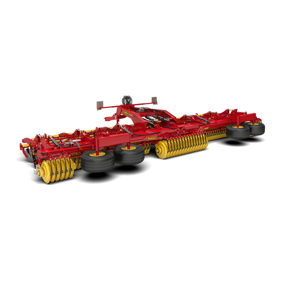
- Page 3 Thank you for choosing Väderstad as your supplier! We hope that our product will increase your profitability and contribute to your having successful crops on your farm. Warm regards, The Stark Family Carrier is a disc cultivator for direct use in the furrows immediately after the harvester or for seedbed preparation before autumn sowing.
-
Page 4: Table Of Contents
Contents Declaration of conformity and ma- Setting the depth stopper ..... 32 chine identity ..........1 Maintenance and service .......33 Declaration of conformity...... 1 Safety when servicing......33 Nameplate .......... 2 Securing the implement for Technical Data ........3 service ..........33 Regular maintenance ...... -
Page 5: Declaration Of Conformity And Machine Identity
Declaration of conformity and machine identity Declaration of conformity and machine identity Declaration of conformity EC declaration of conformity as per the Machinery Directive of the European Parliament and Council 2006/42/EC Väderstad AB, PO Box 85, SE-590 21 Väderstad, SWEDEN hereby declares that the products named below have been manufactured in conformance with the Council’s directive 2006/42/EC. -
Page 6: Nameplate
Declaration of conformity and machine identity Nameplate Model year Seri a l No. / VIN Type Designation Working width Transp ort width Basic weight Max. total weight Max. payload Max. axle load Max. coupling load Mfg. year 498789 Väderstad AB, Box 85, SE-590 21 Väderstad Figure 1.1 A. -
Page 7: Technical Data
Declaration of conformity and machine identity Technical Data Table 1.1 Carrier CR 925 CR 1225 8.94 11.94 Working width (m) Packer width (m) 9.25 12.25 Transport width (m) Transport height (m) Weight with SteelRunner (kg) 10,000 11,700 8,500 9,500 Weight with single SoilRunner (kg) -
Page 8: General Safety Regulations
General safety regulations General safety regulations Obligations and responsibilities Information for which the order is important is indicated using numbered action instructions. These instructions are to be regarded as for guidance only When referring to images, figures are also used in the and entail no responsibility whatsoever on the part of same way as the alphabetical list if the references Väderstad AB and/or its representatives Full responsi-... -
Page 9: Safety Instructions
General safety regulations Safety instructions Never work under the front tool unless it has been secured with jack stands or similar. 2.5.1 Safety during installation Always park the implement on a level and stable Note that poor welding may result in serious surface. - Page 10 General safety regulations Check that the tractor tyres are equipped to cope with the weight of the implement and that they are inflated to the correct pressure. Note that the load exerted on the rear axle of the tractor is high, particularly when transporting by road.
-
Page 11: Warning Decals
General safety regulations Warning decals 2.6.1 Locations of warning decals Figure 2.1 2.6.2 Content of warning decals Make sure that the working area and folding area of the implement are Carefully read through these completely clear. Never walk under a instructions and ensure that suspended section! you have understood their... - Page 12 General safety regulations Following 10–15 km of transport on the road, re-tighten the wheel nuts. Re- tighten the nuts in the same way after changing wheels. Tighten the nuts using a torque wrench. 903815-en-gb; 23.09.2021...
-
Page 13: Moving The Machine When Not Hitched To A Tractor
General safety regulations Moving the machine when not hitched to a tractor If it is necessary to move the machine when not hitched to a tractor, it must be moved fully assembled and in the position for lashing on a transport vehicle! The machine must be transported on a machine trailer, lorry flatbed or another suitable transport vehicle. -
Page 14: Scrapping And Recycling
For more information on how Väderstad AB follows REACH Article 33. Visit www.vaderstad.com/reach Always follow current local recycling regulations and applicable ordinances. 903815-en-gb; 23.09.2021... -
Page 15: Overview Of The Machine
Overview of the machine Overview of the machine Overview of basic machine A. Towing eye B. Support legs C. Drawbar D. System Disc E. Packer F. Scraper G. Wheels 903815-en-gb; 23.09.2021... -
Page 16: Overview Of Accessories/Options
Overview of the machine Overview of accessories/options Figure 3.4 SteelRunner Figure 3.1 CrossCutter (Carrier 925–1225) Figure 3.5 50 mm diameter towing eye (standard). Figure 3.6 40 mm diameter towing eye. Figure 3.2 System CrossBoard Heavy (Carrier 925) Figure 3.7 80 mm diameter ball hitch* *During the work, the machine may give rise to upward force in the tractor’s hitch device. - Page 17 Overview of the machine Figure 3.9 Braking system, Hydraulic/Pneumatic Figure 3.10 Support stand. Mechanical, hydraulic Figure 3.11 BioDrill 903815-en-gb; 23.09.2021...
-
Page 18: Installation
Installation Installation Viscosity The tractor may not be hitched to the machine if the maximum permitted total weight or axle load 400 cSt 50 cSt 20 cSt 10 cSt for the tractor is exceeded. 1. Recommended viscosity range for hydraulic oil. 2. -
Page 19: Hitching And Unhitching
Hitching and unhitching Hitching and unhitching Hitching to the tractor The tractor must always be switched off during connection and disconnection of the hydraulic hoses, otherwise the machine’s hydraulics may be damaged. During the work, the machine may give rise to upward force in the tractor’s hitch device. -
Page 20: Connection Of Hydraulic Hoses
1/2” male connector Wing folding ISO 7241-1, Series A 198830 1/2” male connector Grey CrossBoard ISO 7241-1, Series A CrossBoard only for CR 925 217568 1/2” male connector Grey CrossCutter ISO 7241-1, Series A 1/2” male connector System Disc Blue ISO 7241–1 Series A... -
Page 21: Disconnection And Parking
Hitching and unhitching Disconnection and parking 5.3.2 Lights Always park the implement on a level and stable surface. 1. Secure the support stand. 2. Secure the wheels using the brake pads (B). Figure 5.4 The male connector for the machine lights is connected to the standard external 7-pole trailer connector on the tractor. - Page 22 Hitching and unhitching Figure 5.8 A. Position for support leg B. SystemDisc position 903815-en-gb; 23.09.2021...
-
Page 23: Transport
Transport Transport Brakes The brake system’s main cylinder, brake pads and brake drums are wearing parts. When replacing a component, the entire component must be replaced. 6.1.1 General maintenance prior to each season 1. Check that all cables and hoses are undamaged and 6.1.2 Hydraulic brakes leaktight. - Page 24 Transport 6.1.3.2 Disconnecting the brakes Unhitching and parking must always take place on a flat, firm surface. Figure 6.4 Figure 6.3 1. When unhitching the machine, the service brake is 1. Activate the parking brake by pulling on the lever (A). automatically engaged.
-
Page 25: Switching Between Transport And Working Position
Transport Figure 6.7 Figure 6.5 3. Fold out the machine. The spring brake cylinders use a diaphragm cylinder (A) For larger tractors and crawler tractors, it is not for the travel brake/parking brake and a spring brake section (B) for emergency braking. enough to simply put them into neutral. - Page 26 Transport 6.2.2 Switching to the working position Figure 6.10 Figure 6.13 1. Drive forward and stop. Figure 6.11 6. Whereby the wing sections turn backward, see “Figure 6.10 “ and “Figure 6.11 “. Figure 6.14 2. Lower/push the front tools all the way out using the hydraulic system.
- Page 27 Transport Figure 6.19 Figure 6.16 5. Slowly reverse the tractor until the roller has been 4. The transport lock will now open, see also “8.2 completely folded out, see “Figure 6.17 “ to “Figure Transport lock“ 6.19 “. Figure 6.20 Figure 6.17 6.
- Page 28 Transport Figure 6.22 Figure 6.23 8. Put the tractor in neutral and lower the packer to its working position. Keep the hydraulic lever in the lowered position for a while until the folding cylinder has completely retracted. The packer is now set to the working position.
-
Page 29: General Settings
General settings General settings Horizontal alignment 7.1.2 Frame When checking the parallelism of the frame, the front tool must not be pressed down onto the ground. 7.1.1 Drawbar Figure 7.2 Ensure that the frame is parallel with the ground. 2. The frame angle is adjusted using the hydraulics until it is parallel with the ground, see parallel setting “5.3.1 Dimensions and colour coding on the hydraulic hoses“. - Page 30 General settings At the same time, check “7.2.2 Aligning the System Disc“. 7.2.3 Adjusting the X-disc 7.2.2 Aligning the System Disc If the X-disc is set incorrectly, there is a risk of a ditch or a bank being formed. The piston rod may not be screwed out by more than 20 mm from the lock nut Figure 7.7 Adjust the X-disc as follows:...
-
Page 31: Adjusting The Wheel Angle
General settings Adjusting the scrapers 7.2.5 Spill prevention plates (Applies to CR 1225) 7.4.1 SteelRunner Be careful, there is a risk of crushing! Figure 7.9 The spill prevention plates that are fixed to the outside of Figure 7.11 the System Disc front tool should travel in or just above the ground. -
Page 32: Front Tools
General settings 7.4.2 Scraper blades 7.4.4 Wheel section Figure 7.15 Figure 7.13 The machine is delivered with standard type scraper blades (A). Wider points (B) may be ordered. The part number for these points is indicated in the spare parts manual. The wider point is designed for clay soils and moist conditions with little occurrence of straw, e.g. - Page 33 General settings 7.5.2.2 Setting the straw harrow Figure 7.17 The cultivating angle of the Crossboard shaft can be Figure 7.19 continuously adjusted by using the hydraulic ram which connects to a double-acting hydraulic connection on the Set the height of the straw harrow so that the tines only tractor.
- Page 34 General settings hydraulically driven system, it is easy to adjust the depth from the tractor cab during operation. 903815-en-gb; 23.09.2021...
-
Page 35: Use Of The Machine
Use of the machine Use of the machine Driving instructions Transport lock Figure 8.1 Figure 8.3 The first run should be made immediately after The machine is equipped with a semi-automatic transport harvesting and at 20°–40° to the direction of threshing. lock. -
Page 36: Straw Harrow
Use of the machine Straw harrow Setting the depth stopper 8.3.1 Switching between the working position and transport position To reduce the transport height of the implement, the straw harrow’s wing sections must be folded together before the implement is switched to the transport position. -
Page 37: Maintenance And Service
Maintenance and service Maintenance and service The machine must always be secured before any To maintain the machine’s high level of quality type of service or maintenance work is and operational safety, use only Väderstad commenced. genuine spare parts. The warranty and any claims under it will become void if parts other than genuine parts are used. -
Page 38: Regular Maintenance
Maintenance and service • The use of a degreasing agent will dissolve the waxy Check that the wing sections’ locking hooks are protective coating that is applied during manufacture engaged before carrying out work underneath the to hydraulic couplings, galvanised bolts and other folded up section. -
Page 39: Lubrication Points
Maintenance and service Lubrication points Safety first! Do not crawl under the machine, but rather lubricate from above or support the machine securely on trestles. Figure 9.4 Lubricate according to the intervals in the schedule below and always after washing with high-pressure equipment and at the end of a season. - Page 40 Maintenance and service 9.4.1 Lubrication Points Overview Pos. Lubrication points Interval Number CR 925 Number CR 1225 Packer bearings 500 ha Pos. Lubrication points Interval Number CR 925 Number CR 1225 Implement hitching points’ 500 ha bearings 500 ha Turnbuckles 500 ha Rocker shafts’...
- Page 41 Maintenance and service Pos. Lubrication points Interval Number CR 925 Number CR 1225 Joint bolts, bogie cradle 500 ha Pos. Lubrication points Interval Number CR 925 Number CR 1225 Wheel hubs 500 ha Pos. Lubrication points Interval Number CR 925...
- Page 42 Maintenance and service Pos. Lubrication points Interval Number CR 925 Number CR 1225 Pivot bearing (brake only) 500 ha Pos. Lubrication points Interval Number CR 925 Number CR 1225 Cranks on straw harrow (ac- 500 ha cessory, CR 1225) Pos.
-
Page 43: Drawbar
Maintenance and service Drawbar When the diameter of the hole in the towing eye has increased by 2.5 mm, it has reached its wear limit and it is time to change the eye. 9.5.1 Towing eye When fitting a new towing eye, new bolts (A) must be Never weld a towing eye, as this can drastically used. -
Page 44: Hydraulics
Maintenance and service Hydraulics The hydraulic system must always be bled after servicing. Make sure there is nobody in the immediate working area of the machine. This adjustment must take place without removal of any of the piston rods from the machine. When bleeding the hydraulic system, it is not Figure 9.9 necessary to undo any couplings. -
Page 45: Front Tools
Maintenance and service The highest possible level of cleanliness should be 9.7.1.2 Changing the CrossCuter Knife roller observed when replacing sealing kits. Be careful not to damage any surface of the hydraulic components while working and that all gaskets are mounted correctly. Check the components for abnormal wear and tear, for example burrs or scratches which may indicate the presence of dirt in the hydraulic system or wrongly-weighted components. - Page 46 Maintenance and service 2. Take off the old disc arm and fit a new one (B). Size (Ø mm) Min (Ø mm) 3. Install the rubber rods (C). Wet the rubber rods with soapy water to make them easier to fit. 4.
-
Page 47: Roller Ring Unit
Maintenance and service Roller ring unit 9.9.1 Servicing of SteelRunner Never dismantle a packer ring unit with steel rings. The unit has been pressed together with a force of 4 tonnes. Any attempt to dismantle it Figure 9.19 risks causing injury. If you need to have the unit dismantled, contact your dealer, as special tools 3. -
Page 48: Brakes
Re-tightening of wheel nuts 9.10.3 Tyres and air pressure Check the tyre pressure. See recommendations in “Table 9.2 “. Table 9.2 Modell Transporthjul CR 925 4.0–4.5 CR 1225 4.0–4.5 9.11 Brakes Adjustment of the brakes should be done while Figure 9.22 the tractor hitched to the machine Following 10–15 km of road transportation, retighten the... -
Page 49: Tools
(E). The distance (F) between the pivot (E) and the centre of the hole in the fork (A) must be as in “Table 9.3 “. Table 9.3 CR 925-1225 At the rear wheels (mm) At the front wheels (mm) 9.12 Tools Figure 9.25... - Page 50 Maintenance and service Table 9.4 Dimensions 22 mm Adjustment of master and slave cylinders for the front tool frames 24 mm Adjustment of the outer discs 30 mm Adjustment of the lock nuts for the master and slave cylinders, and adjustment of the turnbuckle on the front drawbar 36 mm...
-
Page 51: Hydraulics System Diagram
Hydraulics system diagram Hydraulics system diagram Figure 10.1 CR925 903815-en-gb; 23.09.2021... - Page 52 Hydraulics system diagram Table 10.1 Hydraulic diagram CR925 Folding cylinder Folding cylinder C3-C8 Liftcylinder System Disc C9-C11 CrossBoard C12-C15 CrossCutter Hydraulic block lift / wing folding Pressure limiter CrossCutter Hydraulic block folding lock Hydraulic block hydraulic lock Djupstoppventil V1–V4 Pilot-operated check valve 903815-en-gb;...
- Page 53 Hydraulics system diagram Figure 10.2 CR1225 903815-en-gb; 23.09.2021...
-
Page 54: Brakes
Hydraulics system diagram Table 10.2 Hydraulic diagram CR1225 C1 – C2 Folding cylinder C3-C8 Liftcylinder System Disc C9-C14 CrossCutter Hydraulic Block Lifting System Disc / Wing Folding Pressure limiter CrossCutter Hydraulic block folding lock Depth stop valve V1–V4 Pilot-operated check valve 10.1 Brakes Figure 10.3... -
Page 55: Pneumatic System Diagram
Pneumatic system diagram Pneumatic system diagram 11.1 Brakes Figure 11.1 Table 11.1 Hydraulics system diagram Connector, red pressure line Connector, yellow control line Line filter Tank Brake valve Retarder valve Spring brake cylinders Diaphragm cylinders Relay valve 903815-en-gb; 23.09.2021... -
Page 56: Troubleshooting
Troubleshooting Troubleshooting Many of the functions of the machine are controlled by a series of electrical, hydraulic and mechanical components. A good way to immediately exclude many of the sources of faults is to first determine whether or not the fault is electrical. - Page 57 903815-en-gb; 23.09.2021...
- Page 58 Väderstad AB SE-590 21 VÄDERSTAD Sweden Phone: +46 142- 820 00 www.vaderstad.com Where farming starts...
Need help?
Do you have a question about the CR 925 and is the answer not in the manual?
Questions and answers