
Related Manuals for Vaderstad Rapid Series


Summary of Contents for Vaderstad Rapid Series
- Page 1 Instructions E-services Rapid Version 1.6.3 903099-en-gb; 19.01.2021 07 Original instructions...
- Page 2 ©Väderstad Holding AB, Väderstad, Sweden 2018 903099-en-gb; 19.01.2021...
-
Page 3: Table Of Contents
Contents General safety provisions ......1 Fertiliser .......... 22 BioDrill ........... 22 Obligations and responsibilities ....1 Radar ..........22 How to read these instructions....1 Oil flow ........... 23 Description of safety symbols ....1 Configuration .........24 Product description........2 Väderstad E-Services......2 Statistics ..........25 Overview ........... -
Page 5: General Safety Provisions
Also consider downloading a new version of the Used to clarify information. instructions when you have updated your software. The instructions are available on our website, www.vaderstad. com. To download to an iPad, see “14 Download • Used to present information in the form of bullet instructions and video“. -
Page 6: Product Description
Product description Product description Väderstad E-Services 4. Väderstad AB’s website contains a list of tested terminals; visit www.vaderstad.com for more information. All machine functions are controlled and monitored from the tractor cab using a control unit. iPad (E-Control) Väderstad offers two different alternatives for controlling and monitoring the machine. - Page 7 Product description 2.6.1 Button functions Figure 2.4 E-Keeper A. Variable adjustment of sown seed amount: hold down the A button and move UP/DOWN using the E and H buttons. B. Variable adjustment of sown fertiliser amount: hold down the B button and move UP/DOWN using the E and H buttons.
-
Page 8: Assembly Instructions
Assembly instructions Assembly instructions Mount E-keeper in the tractor Connecting to ISOBUS Be sure to check for any concealed wiring prior to any drilling in the tractor cab. 1. Fix the dock securely in the tractor cab. The dock should be located within the field of vision when driving forwards. -
Page 9: Pair The Ipad With The E-Keeper
Assembly instructions 4. Connect the black cable to minus and the red cable to plus. Pair the iPad with the E-Keeper In order for an iPad to work with an E-Keeper, they must be paired. If the iPad is used with another E-Keeper or the E-Keeper is replaced, they will need to be re-paired. -
Page 10: Get Started
Get started Get started Connecting with E-Control 4.1.1 If the network is not found automatically If connection to the network does not take place automatically, the network connection must be enabled. This might happen if, for example, you have already connected to another network or you are using an iPad that has not been connected to the network from Gateway before (network unknown). -
Page 11: Download The E-Control Application, Isobus/E-Control
Get started Download the E-Control application, Updating software in Gateway, ISOBUS/E-Control ISOBUS/E-Control Väderstad’s E-Control application is free software that Software is updated by first downloading the new can be downloaded to an iPad from the App Store (Apple software to your iPad from the Internet. When the iPad and the App Store are registered trademarks of Apple then connects to the local network from Gateway, you are Inc.). -
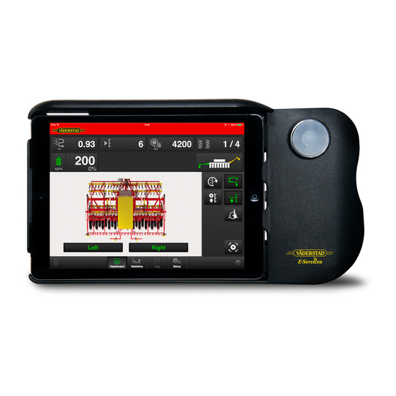
Page 12: The Home Screen
The home screen The home screen The home screen is the view shown whilst operating All The following information is available on the home the information that it is important to monitor is shown screen: here, and all necessary settings can be made here too. A. -
Page 13: Function Buttons
The home screen Function buttons D. Bout marker switching The following settings can be made directly from the Automatic bout marker home screen while driving. Press the button for the switching function you want to access in order to change the setting Position bout marker During normal driving, automatic bout marker switching is used. -
Page 14: Navigation Buttons
The home screen Navigation buttons E. LowLift/HighLift Low-lift position Home screen. This button always takes you back to the home screen. Use Low-lift when drilling. This prevents the machine Statistics. Shows statistics of the machine’s from being raised too much, while allowing proper operation as well as drilling performance operation of the following harrow in the turning patch. -
Page 15: Tank Level
The home screen Tank level The part of the machine for which seed feed is shut off is shown by a white symbol against a grey background. Field F, H and J on the work display, see figure “5.2“. Status output units The screen displays three different levels depending on status: The status of each output unit is indicated in the machine... -
Page 16: General Settings
General settings General settings General settings Tap the navigation button for basic settings, calibration and configuration For daily use no settings need to be entered in The seed drill always has basic factory settings with the this menu. correct machine type, size, etc. When the Gateway device that contains the machine’s memory is replaced, new basic settings must be entered. - Page 17 General settings 6.3.1 External control off 6.3.3 Product offset External Control is switched off. 6.3.2 ISOBUS Task Control Task Control is a GPS-based help function for use in the field. A GPS terminal supporting this function is required for Task Control to work correctly. Contact your local GPS supplier to ensure that the correct functionality is available.
-
Page 18: Tramlining
General settings J. SC Turn On Time = Time compensation for seed A. Select whether or not to enable tramlining. transportation (switch on) B. Select “Automatic” for normal tramlining with both wheel tracks in the bout. Select the interval in field Example: If it takes 4 seconds for seeds to reach the ‘C’. - Page 19 General settings 6.4.4 Open a saved tramline program Left Right Figure 6.12 6.4.2 Managing track program Press B to display a list of saved tramline programs. Open the saved program by selecting its name on the list, “Figure 6.10 “. 6.4.5 Delete a saved tramline program Figure 6.10...
-
Page 20: Alarms
General settings Alarms If an alarm concerns different sections, e.g. right or left seed meter, this is specified with RIGHT/LEFT or BOTH in the alarm text. 6.5.1 Alarm settings In the alarm settings menu, select the machine’s low level sensors for seed, fertiliser and BioDrill (B). An alarm delay (A) in seconds should also be specified here. -
Page 21: Hydraulic Following Harrow
General settings Hydraulic following harrow AutoPilot/AutoCheck (accessory) The following harrow is reached by selecting hydraulic following harrow in the configuration, see “8 Configuration“ and activating the following harrow in the general settings, see “6.2 General settings“. The button is now shown on the home screen. Press this button to open the menu for setting the following harrow. - Page 22 General settings Height above ground is measured using trailing runners • When the soil is too coarse and the soil clods too mounted on the drill drawbar. The trailing runners’ large, the sliding runners will travel on top of the measurement points are placed at the centre of the drill, clods.
- Page 23 General settings Figure 6.22 Figure 6.23 Setting the hydraulic system Selecting adjustment sensitivity A. First, select the hydraulic system type used by the C. The desired adjustment sensitivity is entered using tractor. • If a tractor uses a constant oil flow system, which (F) in the AutoPilot system menu on the home means that the tractor’s hydraulic pump has a screen (“Figure 6.23 “) or, alternatively, in settings,...
- Page 24 General settings Adjust as follows: 1. Set the drilling depth as usual using the Control system. 2. Get down from the tractor and visually check the drilling depth to make sure it is correct. 3. Drive the machine at normal speed and lowered to the drilling position.
-
Page 25: Calibration
Calibration Calibration Figure 7.2 Figure 7.1 Display Calibration of delivered seed A. Calculates the number of pulses. B. Calculates the number of pulses/kg. (You can also specify pulses/kg manually by pressing the row and Calibration of fertiliser entering the value in the pop-up window). Settings in the calibration menu Calibration of BioDrill C. -
Page 26: Fertiliser
Calibration Radar The calibration result becomes the baseline value. Always check the actual feed rate on the field. If necessary correct the pulses/kg. Example: If the actual sown amount is 10% too low, increase the pulses/kg by 10%. Note the set sown amount, pulses/kg and the actual sown amount for future use. -
Page 27: Oil Flow
Calibration Oil flow 2. Mechanically activate the left and right half machine shut-offs on the machine in order to prevent feed output during the calibration of the oil flow. It is important to calibrate the oil flow to make sure that you do not drive with either too high or too low a flow. -
Page 28: Configuration
Configuration Configuration The seed drill always has basic factory configuration J. Pre-emergence bout marker. settings with the correct machine type, size, etc. When the • Gateway device that contains the machine’s memory is • Pre-emergence bout marker (accessory) replaced, a new basic configuration must be made. In the •... -
Page 29: Statistics
Statistics Statistics Go to the statistics menu by pressing amount of fertiliser fed out amount of BioDrill fed out Reset the figure Figure 9.1 Statistics The statistics menu shows statistics for the current sowing operation, for the current season and for the total service life of the seed drill, see section (A). -
Page 30: Use In The Field
Use in the field Use in the field 10.1 Variable sown amount A. Steps back in the tramlining program B. Steps forward in the tramlining program By pressing the field for the seed application rate in the C. Restarts the tramlining program on 1 work display, a pop-up window for variable application D. -
Page 31: Information
Information Information Pressing the Information button on the home screen will take you to a page containing alarm history information and detailed information on WorkStation inputs and outputs. 11.1 Alarm history Pressing the Alarm History button in the top menu row will take you to a page containing alarm history information for the last 100 alarms. -
Page 32: Workstation, Inputs And Outputs
Information 11.2 WorkStation, inputs and outputs. Pressing the WorkStation 1 and WorkStation 2 buttons in the top menu row will take you to pages containing detailed information on WorkStation inputs and outputs. The green icon indicates which information is being displayed. Figure 11.2 WorkStation 1, inputs Inputs. - Page 33 Information Figure 11.3 WorkStation 1, outputs Figure 11.4 WorkStation 1, information 903099-en-gb; 19.01.2021...
- Page 34 Information Figure 11.5 Workstation 2, inputs Figure 11.6 Workstation 2, outputs 903099-en-gb; 19.01.2021...
- Page 35 Information Figure 11.7 WorkStation 2, information 903099-en-gb; 19.01.2021...
-
Page 36: Alarm List
Alarm list Alarm list 21. Seed feed rotation LH If the metering units do not move: Check that the toothed coupling between the hydraulic motor and the feed shaft is in the correct position and intact. If the alarm appears although the Check the alert time that has been programmed. - Page 37 Alarm list If the metering units do not move: See alarm no. 31 If the alarm appears although the See alarm no. 31 seed meters: 33. Seed feed, BioDrill rotation LH and RH This alarm is triggered if the left and See alarm no.
- Page 38 Alarm list 221. WorkStation 1 not connected If Gateway loses contact with Check the cabling between Gateway and WorkStation. WorkStation 1 during operation: Check that the cable is not trapped or otherwise damaged. Check the condition of the connectors. If the machine has a WS2 —check the connector on WS2 231.
- Page 39 Alarm list 453. Fertiliser tramlining LH and See alarm no. 451 461. BioDrill tramlining LH Check the sensor’s cable, contacts and connections. Check the sensor. 462. BioDrill tramlining RH Check the sensor’s cable, contacts and connections. Check the sensor. 463. BioDrill tramlining LH and RH Check the sensor’s cable, contacts and connections.
-
Page 40: Electrical System
Electrical system Electrical system 13.1 RD 300 – 400 S/C WS1 Port Function Type Level Guard, Seed Analogue In Level Guard, Seed Digital In Level Guard, Seed 12 V Level Guard, Seed Ground Level Guard, Fertilizer Analogue In Level Guard, Fertilizer Digital In Level Guard, Fertilizer 12 V... - Page 41 Electrical system WS1 Port Function Type Tramline Seed Left Digital Out Tramline Seed Left 12 V Rotation Guard, Seed Left Tramline Seed Left Ground Rotation Guard, Seed Left Level Guard, BioDrill Digital In Level Guard, BioDrill Digital In Level Guard, BioDrill 12 V Level Guard, BioDrill Ground...
- Page 42 Electrical system Tramline Fertilizer Right / Rotation Digital In Guard, Fertilizer Right (RDC) Tramline BioDrill Right (RDS) Tramline Fertilizer Right (RDC) Digital Out Tramline BioDrill Right (RDS) Tramline Fertilizer Right / Rotation 12 V Guard, Fertilizer Right (RDC) Tramline BioDrill Right (RDS) Tramline Fertilizer Right / Rotation Ground Guard, Fertilizer Right (RDC)
- Page 43 Electrical system 12 V Fertilizer Motor speed, output (RDC) Ground BioDrill Motor speed, output (RDS) Rotation Guard, BioDrill Left Digital In Rotation Guard, BioDrill Left 12 V Rotation Guard, BioDrill Left Ground Mini-remote, plus sign Analogue In Mini-remote, seed sign Digital In 12 V Mini-remote...
- Page 44 Electrical system Tramline BioDrill Left (RDC) Digital In Tramline BioDrill Left (RDC) Digital Out Tramline BioDrill Left (RDC) 12 V Tramline BioDrill Left (RDC) Ground Digital In PWM Out Following harrow, directional valve 12 V Following harrow, directional valve Ground Digital In Following harrow, transport lock PWM Out...
-
Page 45: Download Instructions And Video
Download instructions and video Download instructions and video To download instructions and videos to your iPad, it must be connected to the Internet. The machine's software is updated continuously and to ensure that you have access to the latest version of the instructions, it is also possible to download both the instructions and Quick start videos directly to your iPad. -
Page 46: Viewing On Ipad
Download instructions and video Figure 14.5 Figure 14.7 Click on the line to open the document or video 7. To download the document, click on the icon on the right-hand end of each row. When a document is open (not video), you can use three different help functions to find your way in the document 8. -
Page 47: Updating Previously Downloaded Files
Download instructions and video 14.2 Updating previously downloaded files The symbol is only visible when you are connected to the Internet. Figure 14.10 If there is a new version of previously downloaded instructions or video, the icon will be lit next to the instructions or video that can be replaced. - Page 48 Väderstad AB SE-590 21 VÄDERSTAD Sweden Phone: +46 142- 820 00 www.vaderstad.com Where farming starts...
Need help?
Do you have a question about the Rapid Series and is the answer not in the manual?
Questions and answers
I have a warning that is rotation guard biodrill. So it stops the fertiliser coming out. How to fix please
To fix the rotation guard issue on a Vaderstad Rapid Series BioDrill that stops fertilizer from coming out, follow these steps:
1. Check Power Supply – Ensure that the Rotation Guard (BioDrill Left) is receiving 12V power (Pin 24-3) and has a proper ground connection (Pin 24-4).
2. Inspect Sensor Connection – Verify that the Rotation Guard (BioDrill Left) Digital Input (Pin 24-1) is properly connected and not loose or damaged.
3. Calibration Check – The BioDrill calibration follows the same procedure as seed output calibration. Ensure that the correct calibration settings are applied.
4. Look for Error Messages – Check the system for any alarm messages indicating an issue with the Rotation Guard.
5. Test the Sensor – If the sensor is faulty, replace it to restore proper operation.
6. Verify Firmware and Software Settings – Ensure that the system software is up to date and configured correctly.
If the issue persists, consult the electrical system diagram and troubleshooting section for further diagnostics.
This answer is automatically generated