
Related Manuals for Vaderstad Cultus Series


Summary of Contents for Vaderstad Cultus Series
- Page 1 Cultus series CS 300-400 Manufacturing No. 10 400- Instructions 900290-en 11.07.2011 ver. 3 Original instructions...
- Page 2 11.07.2011 ver. 3...
-
Page 3: Table Of Contents
CR 420-820 Safety regulations Before using the implement ..............7 Warning decals ................... 8 Other safety regulations ............... 9 Retightening of screw connections ............11 Machine label ..................12 Moving the machine when not hitched to a tractor ......... 13 Instructions and settings Tractor ..................... - Page 4 11.07.2011 ver. 3...
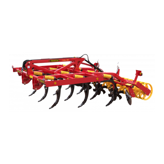
- Page 5 CS 300-400 The Väderstad Cultus 300-400 is intended for stubble cultivation down to a maximum working depth of 25 cm. The cultivator has a number of optional features. As a result, it can be adapted for different soil types and cultivation requirements. The cultivator is intended for use together with tractors up to the recommended maximum output according to the table below.
- Page 6 EC DECLARATION OF CONFORMITY FOR THE MACHINE in accordance with the EU Machinery Directive 2006/42/EC Väderstad-Verken AB, P.O. Box 85, SE-590 21 Väderstad, SWEDEN hereby confirms that the cultivation tools hereunder have been manufactured in accordance with the Council Directive 2006/42/EC. The above declaration covers the following machines: CS 300, CS 350 and CS 400, manufacturing no.
-
Page 7: Safety Regulations
CS 300-400 Safety regulations Before using the implement Always pay extra attention to the instructions or diagram when you see this symbol. Figure 1.1 This implement is intended for cultivating arable land. Learn to handle the implement carefully and correctly. It could be dangerous in the wrong hands and if used without taking proper care. ! The CS 300-350 is intended for tractors up to 160 hp (118 kW). -
Page 8: Warning Decals
Safety regulations Warning decals Figure 1.2 Read the instructions carefully and make sure you understand them. Do not stand between the tractor and the implement when the tractor is being reversed to hitch the implement. 1.2.1 Locations of warning decals Figure 1.3 11.07.2011 ver. -
Page 9: Other Safety Regulations
CS 300-400 Other safety regulations ! VERY IMPORTANT! Retighten screw connections according to the table. See “1.4 Retight- ening of screw connections” see page 11 . • As the implement is heavy, front counterweights should normally be mounted on the tractor. Always ensure that the tractor has a sufficient load on the front axle for safe driving. - Page 10 Safety regulations • Any welding work on the machine should maintain a professional standard. Incorrect welding may result in serious injuries or possibly fatal injuries. If in doubt, contact a professional welding service for proper instructions. • Never stand under the implement if it is only secured with the tractor’s three-point lift! The section “4.1 Securing implement during service, hydraulically mounted”...
-
Page 11: Retightening Of Screw Connections
CS 300-400 Retightening of screw connections Figure 1.5 ! Retighten the screw connections (A) between drawbar and chassis after the first day of opera- tion. Tighten the screw connections to a torque of 550 Nm. Use a torque wrench. ! The screw connections (B) in the cultivator tine linkage must be retightened after the first day of operation and thereafter at least once per season. -
Page 12: Machine Label
Safety regulations Machine label Figure 1.7 Machine type Serial number (Always state the serial number of your machine when ordering spare parts and in case of serv- icing or warranty claims.) Year of manufacture Working width Transport width Tare weight of the basic machine Maximum total weight Maximum permitted payload Maximum permitted axle load... -
Page 13: Moving The Machine When Not Hitched To A Tractor
CS 300-400 Moving the machine when not hitched to a tractor NOTE! If the machine must be moved when not hitched to a tractor,it must be transported on a machine trailer or lorry flatbed! Mounted machines must be lifted onto and off the transport vehicle using a crane, whilst semi- mounted machines must be rolled onto and off the transport vehicle using a tractor. - Page 14 Safety regulations 1.6.2 Rolling on and off of semi-mounted CS 300-400 1 Raise the machine to the full lifting height. 2 Reverse the machine lengthwise onto the trailer or flatbed. If using a flatbed, a ramp, loading pier or similar will be required. Take great care. Check that no machine parts are damaged during loading.
-
Page 15: Instructions And Settings
CS 300-400 Instructions and settings Tractor ! The CS 300-350 is intended for tractors up to 160 hp (118 kW). The CS 400 is intended for tractors up to 200 hp (147 kW). The use of tractors with higher outputs can result in more rapid wear of the implement. -
Page 16: Hitching And Unhitching The Implement
Instructions and settings Hitching and unhitching the implement Figure 2.1 2.2.1 Hitching Hitch the implement to the tractor and connect any hydraulic hoses. Do not stand between the trac- tor and the implement when the tractor is being reversed to hitch the implement! 2.2.2 Unhitching When unhitching the machine, it is important to ensure that all the tines have roughly the same... - Page 17 CS 300-400 2.2.3 Choice of coupling points Figure 2.2 The implement is adapted for a category II or III three-point coupling. In order to minimise the lifting power requirement, the top rod should be mounted in a high cou- pling point on the tractor and a low coupling point on the implement. The round hole (A) is used if you want to use the length of the top rod to adjust the height of the front part of the implement.
-
Page 18: Setting The Levelling Units
Instructions and settings Setting the levelling units Figure 2.4 The height of the levelling units is adjusted using a crank handle. The crank handle has two alter- native mounting points in the levelling units, so that optimum height adjustment should always be possible. - Page 19 CS 300-400 2.3.1 Adjustable outer levelling discs Figure 2.6 Individually adjustable levelling discs can be found outermost on either side. These enable opti- mum levelling in the corridors between each driven pass. Depending on working depth, soil type, etc., it may be appropriate to perform adjustment to avoid the formation of trailing lea lines or fur- rows.
-
Page 20: Adjusting The Working Depth Of The Tines, Hydraulically Mounted
Instructions and settings Adjusting the working depth of the tines, hydraulically mounted Figure 2.8 Figure 2.9 The working depth of the tines is determined by the setting of the compaction roller. The compac- tion roller is adjusted with the aid of a rod (A). The rod can be supplied with clips (B) to secure the end position. -
Page 21: Adjusting The Working Depth Of The Tines, Trailed
CS 300-400 Adjusting the working depth of the tines, trailed Figure 2.10 Figure 2.11 The working depth of the tines is determined by the setting of the compaction roller. The compac- tion roller is adjusted with the aid of the hydraulic cylinder (A). The ram rod can be supplied with clips (B) to secure the cylinder’s end position. -
Page 22: Adjusting Parallel Alignment, Hydraulically Mounted
Instructions and settings Adjusting parallel alignment, hydraulically mounted Figure 2.12 The height of the front part of the implement is adjusted with the length of the top rod or the height of the hydraulic lifting arms, depending on which coupling point has been selected in the imple- ment’s tower, see “2.2.3 Choice of coupling points”... -
Page 23: Adjusting Parallel Alignment, Trailed
CS 300-400 Adjusting parallel alignment, trailed Figure 2.13 The parallel alignment of the implement is determined by the height of the tractor’s lifting arms. When driving in the field, adjustment takes place when checking that the implement is being pulled parallel with the ground. NOTE! Poor parallel alignment can result in the implement being unstable when in motion. -
Page 24: Adjusting The Scrapers
Instructions and settings Adjusting the scrapers Scrapers for rubber ring compactors 2-16 mm Figure 2.14 Adjust the scrapers to ensure the gap between the tips and the rubber rings is 2-16 mm. The rec- ommended basic setting is 6 mm. If the rubber compactor does not run cleanly, adjust the scrapers in steps close to the compaction roller, although no closer than 2 mm. -
Page 25: Operating Instructions And Cultivating Tips
CS 300-400 Operating instructions and cultivating tips Driving directions Figure 3.1 1 The first pass should take place immediately after harvesting and at an angle of 20°-40° to the harvesting direction. 2 The second pass should take place at 20°-40° to the previous pass. When turning on the headland, you can choose only to raise the towed machine at the three-point linkage. - Page 26 Operating instructions and cultivating tips The final pass before sowing must not take place in the same direction as the intended sowing di- rection. Finish by driving as wide on the headland as you subsequently intend to sow this area, to give an indication of where the bouts are to start and finish.
-
Page 27: Choice Of Tips, Wing Cutters And Guide Rails
CS 300-400 Choice of tips, wing cutters and guide rails 3.2.1 Tips and wing cutters Figure 3.3 The Väderstad Cultus is fitted as standard with type (A) 80 mm wide tips. Alternatively, tips with a width of 50 mm (B) and 120 mm (C) are available, as well as a 210 mm wide goose foot tip (D). -
Page 28: Gradually Increase The Cultivation Depth
Operating instructions and cultivating tips 3.2.2 Guide rails Figure 3.4 The machine is fitted as standard with a MixIn shin of type (A). The MixIn shin throws the soil forwards so that the soil achieves a rotating movement, mixing in plant remains time and again in a single pass. -
Page 29: Stable Movement And Even Cultivation
CS 300-400 Stable movement and even cultivation NOTE! In order to achieve stable movement and an even cultivation result, it is important to ensure correct parallel alignment. For hydraulic mounting see “2.6 Adjusting parallel alignment, hydrau- lically mounted” see page 22 . For trailed mounting see“2.7 Adjusting parallel alignment, trailed”... -
Page 30: Levelling Discs
Operating instructions and cultivating tips Levelling discs Figure 3.7 Levelling units are located outermost on either side. Depending on the working depth and the ground conditions, the links with the levelling units can be secured or remain flexible. A flexible link that produces less wear and tear is recommended. -
Page 31: Service And Maintenance
CS 300-400 Service and maintenance Figure 4.1 Securing implement during service, hydraulically mounted ! Never stand under the implement if it is only secured with the tractor’s three-point lift! 1 Raise the machine in the lifting arms. 2 Secure the implement as far back as possible using two trestles (B) that are adapted for the weight, and ensure that the surface is stable. -
Page 32: General Information Regarding Service
Service and maintenance General information regarding service • Do not stand near hydraulic hoses under pressure. Recover any spilled oil after performing service on the hydraulic system. • Always use Väderstad original spare parts to maintain the quality and reliability of the imple- ment. - Page 33 CS 300-400 4.4.1 Lubrication chart, CS 300-400 Table 4.1 Pos. Lubrication points Interval Lubricant Number Roller bearings 100 ha Grease Roller section mounting 100 ha Grease Hydraulic cylinder’s ram rod head 100 ha Grease Mounting for tines 100 ha Grease 2/tine Figure 4.4 4.4.2...
-
Page 34: Retightening And Checking The Tine Linkage
Service and maintenance Retightening and checking the tine linkage Figure 4.6 The screw connections in the tine linkage must be retightened after the first day of operation and thereafter at least once per season. If retightening is not carried out, considerable wear will occur in the tines’... -
Page 35: Dismantling The Parts In The Cultivator Tine Suspension System
CS 300-400 Dismantling the parts in the cultivator tine suspension system Figure 4.8 When dismantling the cultivator tines’ springs, the spring locking bolts (A) must be fully loos- ened. The springs have a very high clamping force. By loosening the spring locking bolt, the pres- sure on the springs is relieved and parts can be replaced. -
Page 36: Service On Rubber Compactor
Service and maintenance Service on rubber compactor Apart from greasing of the bearings, the roller ring units usually do not require any maintenance. If there should ever be a need for disassembly, please contact the dealer. Service on steel compactor Figure 4.10 Apart from greasing of the bearings, the roller ring units do not normally require any maintenance. -
Page 37: Hydraulic Diagram
CS 300-400 Hydraulic diagram CS 300-400 Figure 5.1 11.07.2011 ver.3... -
Page 38: Technical Data
Technical data Technical data CS 300-350 with steel compactor Implement, CS Working width (m) Transport width (m) Height (m) Transport height, approximate (m) Weight (kg) 2200 2400 Centre of gravity, (A) according to “Figure 6.1” 2200 2200 (mm) Power requirement (hp) 100-140 120-160 ! The machine is optimised for use together with a tractor of up to 160 hp (118 kW) when work-... -
Page 39: Cs 300-400 With Rubber Compactor
CS 300-400 CS 300-400 with rubber compactor Implement, CS Working width (m) Transport width (m) Height (m) Transport height, approximate (m) Weight, without drawbar (kg) 2200 2400 Weight, with drawbar (kg) 2400 2600 2800 Centre of gravity without drawbar, (A) according to 2130 2120 “Figure 6.2”... -
Page 40: Cs 300-350 With Cage Roller
Technical data CS 300-350 with cage roller Table 6.1 Implement, CS Working width (m) Transport width (m) Height (m) Transport height, approximate (m) Weight (kg) 1800 2000 Centre of gravity, (A) according to “Figure 6.3”(mm) 1870 1840 Power requirement (hp) 100-140 120-160 ! The machine is optimised for use together with a tractor of up to 160 hp (118 kW) when work-... - Page 42 590 21 VÄDERSTAD S-590 21 VÄDERSTAD SWEDEN Telefon 0142-820 00 Telephone +46 142 820 00 Telefax 0142-820 10 Telefax +46 142 820 10 www.vaderstad.com...
Need help?
Do you have a question about the Cultus Series and is the answer not in the manual?
Questions and answers