Table of Contents
Advertisement
Quick Links
Advertisement
Table of Contents

Related Manuals for Advantech WISE-4000 Series


Summary of Contents for Advantech WISE-4000 Series
- Page 1 User Manual WISE-4000 Series IoT Ethernet I/O Module...
- Page 2 No part of this manual may be reproduced, copied, translated or transmitted in any form or by any means without the prior written permission of Advantech Co., Ltd. Information provided in this manual is intended to be accurate and reliable. How- ever, Advantech Co., Ltd.
- Page 3 The date for certificate issue: 2016 Type of identification: Wi-Fi I/O Technical Support and Assistance Visit the Advantech web site at www.advantech.com/support where you can find the latest information about the product. Contact your distributor, sales representative, or Advantech's customer service center for technical support if you need additional assistance.
- Page 4 The sound pressure level at the operator's position according to IEC 704-1:1982 is no more than 70 dB (A). DISCLAIMER: This set of instructions is given according to IEC 704-1. Advantech disclaims all responsibility for the accuracy of any statements contained herein.
-
Page 5: Table Of Contents
Contents Chapter Product Overview ........1 Introduction ....................2 Feature Highlights ..................2 1.2.1 RESTful Web Service ..............2 1.2.2 Data Storage Function ..............3 1.2.3 IoT Cloud Function................ 3 Series Family and Specifications ............. 4 1.3.1 Series Family ................4 Mechanical Design and Dimensions ............ - Page 6 Figure 2.14WISE-4012E Digital Input Wiring Diagram....22 Figure 2.15WISE-4012E Relay Output Wiring Diagram..... 22 2.5.3 Pin Assignment................23 Figure 2.16WISE-4012E Pin Assignment........23 2.5.4 Block Diagram ................23 Figure 2.17WISE-4012E Block Diagram ........23 WISE-4012....................24 2.6.1 I/O Specification................24 2.6.2 Application Wiring ...............
- Page 7 WISE-4050 Wireless Modbus Mapping Table ........110 WISE-4051 Wireless Modbus Mapping Table ........112 WISE-4060 Wireless Modbus Mapping Table ........114 Appendix B REST for WISE-4000 Series ....117 Introduction ................... 118 REST Resources for WISE-4000 Series..........119 B.2.1 Digital Input ................119 WISE-4000 User Manual...
- Page 8 B.2.2 Digital Output ................124 B.2.3 Analog Input................129 B.2.4 RS-485 Port Expansion Data............ 135 B.2.5 Data Logger ................143 WISE-4000 User Manual viii...
-
Page 9: Chapter 1 Product Overview
Chapter Product Overview... -
Page 10: Introduction
Introduction WISE-4000 series is an Ethernet-based wired or wireless IoT device, which inte- grated with IoT data acquisition, processing, and publishing functions. Except various I/O type offering, WISE-4000 series provides data pre-scaling, data logic, and data logger functions. These data can be access via mobile devices and be published to cloud with security in anytime and anywhere. -
Page 11: Data Storage Function
1.2.2 Data Storage Function The internal flash of the WISE module can log up to 10,000 data samples with a time stamp. The I/O data can be logged periodically, and when the I/O status changes. Once the memory is full, users can choose to overwrite the old data to ring log or just stop the log function. -
Page 12: Series Family And Specifications
Series Family and Specifications 1.3.1 Series Family Interface Model Description 6-ch Input/Output WISE-4012E IoT Wireless I/O Module for IoT Developers 4-ch Universal Input and 2-ch Digital Output WISE-4012 IoT Wireless I/O Module 4-ch Digital Input and 4-ch Digital Output WLAN WISE-4050 IoT Wireless I/O Module 8-ch Digital Input... -
Page 13: Mechanical Design And Dimensions
Mechanical Design and Dimensions 1.4.1 WISE-4000 Wireless Series Dimensions 1.4.2 WISE-4000/LAN Dimensions WISE-4000 User Manual... -
Page 14: Switch
Switch Switch Description Position ON (Default) Normal Mode Initial Mode Operation Mode Dry Contact Wet Contact DI Type (Ch0~3) Dry Contact Wet Contact Dry Contact Wet Contact DI Type (Ch4~7) Dry Contact Wet Contact Note 1 After the position 1 of SW1 been changed, user need to power on the module again to apply the operation mode Note 2 SW2 is for WISE-4051, WISE-4050(/LAN), and WISE-4060(/LAN), all 4 channels have to be configured to dry contact or wet contact in the same... -
Page 15: Certification And Safety Standard
Certification and Safety Standard WISE-4000/LAN Series – FCC Part 15 Class A – IC ICES-003 – EN 55011 (Group 1, CLASS A) – EN 55022 – EN 61000-6-4 – EN 61000-6-2 – IEC 61000-4-2 – IEC 61000-4-3 – IEC 61000-4-4 –... -
Page 16: Package Information
Package Information WISE-4000 Wireless Series WISE-4000 Module with bundle antenna and terminal connector x1 Mounting bracket x1 Quick startup manual with China RoHS declare WISE-4000/LAN Series WISE-4000/LAN Module Mounting bracket x1 Quick startup manual with China RoHS declare WISE-4012 ... -
Page 17: Chapter 2 Product Specifications
Chapter Product Specifications... -
Page 18: General Specifications
General Specifications WLAN Interface Standard Conformance: – 802.11b – 802.11g – 802.11n (2.4GHz only) Network Modes: – Limited AP (Wireless Server) – Station/Infrastructure (Wireless Client) Transmission Distance: 110 meters (In open areas with bundled external antenna) Wireless Security: WPA2 Personal &... - Page 19 Storage Humidity: 0~95% RH (non-condensing) Note! Equipment will operate below 30% humidity. However, static electricity problems occur much more frequently at lower humidity levels. Make sure you take adequate precautions when you touch the equipment. Consider using ground straps, anti-static floor coverings, etc. if you use the equipment in low humidity environments.
-
Page 20: Wise-4010/Lan
WISE-4010/LAN 2.2.1 I/O Specification Current Input – Channel: 4 – Resolution: 12-bit – Sampling Rate: 10/100 Hz/channel – Accuracy: ±0.2% of FSR @ 25°C – Input Range: 0~20 mA, 4~20 mA (Select by Web Configuration) Input Impedance: 120 Ω –... -
Page 21: Application Wiring
2.2.2 Application Wiring Figure 2.1 WISE-4010/LAN Current Input Wiring Diagram Figure 2.2 WISE-4010/LAN Digital Output Wiring Diagram WISE-4000 User Manual... -
Page 22: Pin Assignment
2.2.3 Pin Assignment Figure 2.3 WISE-4010/LAN Pin Assignment 2.2.4 Block Diagram Figure 2.4 WISE-4010/LAN Block Diagram WISE-4050/LAN 2.3.1 I/O Specification Digital Input – Channel: 4 – Logic level –Dry Contact 0: Open 1: Close to DI COM –Wet Contact 0: 0~3 V or -3~0 V 1: 10~30 V or -30~-10 V... -
Page 23: Application Wiring
Digital Output – Channels: 4 – Open collector to 30 V, 400 mA max. for resistance load – Inductive loads require an external diode to eliminate back-EMF when the DO is turned off – Isolation: 3,000 V ): 0.7 Ω (max.) @ 400mA, 25°C, 10V –... -
Page 24: Pin Assignment
2.3.3 Pin Assignment Figure 2.7 WISE-4050/LAN Pin Assignment 2.3.4 Block Diagram Figure 2.8 WISE-4050/LAN Block Diagram WISE-4000 User Manual... -
Page 25: Wise-4060/Lan
WISE-4060/LAN 2.4.1 I/O Specification Digital Input – Channel: 4 – Logic level – Dry Contact 0: Open 1: Close to DI COM – Wet Contact 0: 0~3 V or -3~0 V 1: 10~30 V or -30~-10 V (3 mA min.) –... -
Page 26: Application Wiring
2.4.2 Application Wiring Figure 2.9 WISE-4060/LAN Digital Input Wiring Diagram Figure 2.10 WISE-4060/LAN Relay Output Wiring Diagram WISE-4000 User Manual... -
Page 27: Pin Assignment
2.4.3 Pin Assignment Figure 2.11 WISE-4060/LAN Pin Assignment 2.4.4 Block Diagram Figure 2.12 WISE-4060/LAN Block Diagram WISE-4000 User Manual... -
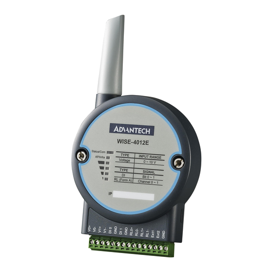
Page 28: Wise-4012E
WISE-4012E 2.5.1 I/O Specification Voltage Input – Channel: 2 – Resolution: 12-bit – Sampling Rate: 10 Hz (Total) – Accuracy: ±0.1 V – Input Range: 0~10 V – Input Impedance: 100 kΩ – Supports Data Scaling and Averaging Digital Input –... - Page 29 Note! The analog input channel of the WISE-4012E does not support inverted voltage protection, note that the input voltage should within 0~10V WISE-4000 User Manual...
-
Page 30: Application Wiring
2.5.2 Application Wiring Figure 2.13 WISE-4012E Voltage Input Wiring Diagram Figure 2.14 WISE-4012E Digital Input Wiring Diagram Figure 2.15 WISE-4012E Relay Output Wiring Diagram WISE-4000 User Manual... -
Page 31: Pin Assignment
2.5.3 Pin Assignment Figure 2.16 WISE-4012E Pin Assignment 2.5.4 Block Diagram Figure 2.17 WISE-4012E Block Diagram WISE-4000 User Manual... -
Page 32: Wise-4012
WISE-4012 2.6.1 I/O Specification Universal Input – Channel: 4 – Resolution: 16-bit – Sampling Rate* –Universal Input 10Hz (Total) –Digital Input 2Hz (Per Channel) – Accuracy –Voltage ±0.1% of FSR –Current ±0.2% of FSR** – Input Type and Range –... -
Page 33: Application Wiring
2.6.2 Application Wiring Figure 2.18 WISE-4012 Analog Input Wiring Diagram Figure 2.19 WISE-4012 Digital Input Wiring Diagram Figure 2.20 WISE-4012 Digital Output Wiring Diagram WISE-4000 User Manual... -
Page 34: Pin Assignment
2.6.3 Pin Assignment Figure 2.21 WISE-4012 Pin Assignment 2.6.4 Block Diagram Figure 2.22 WISE-4012 Block Diagram WISE-4000 User Manual... -
Page 35: Wise-4050
WISE-4050 2.7.1 I/O Specification Digital Input – Channel: 4 – Logic level –Dry Contact 0: Open 1: Close to DI COM –Wet Contact 0: 0~3 V or -3~0 V 1: 10~30 V or -30~-10 V (3 mA min.) –All 4 channels should be configured to dry contact or wet contact in the same time –... -
Page 36: Application Wiring
2.7.2 Application Wiring Figure 2.23 WISE-4050 Digital Input Wiring Diagram Figure 2.24 WISE-4050 Digital Output Wiring Diagram 2.7.3 Pin Assignment Figure 2.25 WISE-4050 Pin Assignment WISE-4000 User Manual... -
Page 37: Block Diagram
2.7.4 Block Diagram Figure 2.26 WISE-4050 Block Diagram WISE-4051 2.8.1 I/O Specification Digital Input – Channel: 8 – Logic level –Dry Contact 0: Open 1: Close to DI COM –Wet Contact 0: 0~3 V or -3~0 V 1: 10~30 V or -30~-10 V (3 mA min.) –Channel 0~3 should be configured to dry contact or wet contact in the same... -
Page 38: Application Wiring
2.8.2 Application Wiring Figure 2.27 WISE-4051 Digital Input Dry Contact Wiring Diagram Figure 2.28 WISE-4051 Digital Input Wet Contact Wiring Diagram WISE-4000 User Manual... -
Page 39: Pin Assignment
Figure 2.29 RS-485 Port Wiring Diagram 2.8.3 Pin Assignment Figure 2.30 WISE-4051 Pin Assignment 2.8.4 Block Diagram Figure 2.31 WISE-4051 Block Diagram WISE-4000 User Manual... -
Page 40: Wise-4060
WISE-4060 2.9.1 I/O Specification Digital Input – Channel: 4 – Logic level –Dry Contact 0: Open 1: Close to DI COM –Wet Contact 0: 0~3 V or -3~0 V 1: 10~30 V or -30~-10 V (3 mA min.) – Isolation: 3,000 V –... -
Page 41: Application Wiring
2.9.2 Application Wiring Figure 2.32 WISE-4060 Digital Input Wiring Diagram Figure 2.33 WISE-4060 Relay Output Wiring Diagram 2.9.3 Pin Assignment Figure 2.34 WISE-4060 Pin Assignment WISE-4000 User Manual... -
Page 42: Block Diagram
2.9.4 Block Diagram Figure 2.35 WISE-4060 Block Diagram WISE-4000 User Manual... -
Page 43: Hardware Installation
Chapter Hardware Installation... -
Page 44: Interface Introduction
Interface Introduction Mounting WISE-4000 modules are designed as compact units and are allowed to be installed in the field site under the following methods. 3.2.1 DIN-Rail Mounting The WISE-4000 module can also be fixed to the cabinet by using mounting rails. You need to assemble the DIN rail adapter to WISE-4000 module with flathead screw driver as below. - Page 45 Figure 3.3 Mounting on the DIN-Rail Figure 3.4 Rear View of DIN-Rail Mounting WISE-4000 User Manual...
-
Page 46: Wall Mounting
3.2.2 Wall Mounting Each WISE-4000 module is packed with a plastic wall mounting bracket. User can refer the bracket dimension and assembling figure to configure an optimal placement in a wall, panel, or cabinet. Figure 3.5 Mounting Kit Dimensions WISE-4000 User Manual... - Page 47 Figure 3.6 Wall Mounting Figure 3.7 Wall Mounting Finished WISE-4000 User Manual...
-
Page 48: Stack Mounting
3.2.3 Stack Mounting Figure 3.8 Stack Mounting Figure 3.9 Finished Stack Mounting WISE-4000 User Manual... -
Page 49: Wiring & Connections
Wiring & Connections This section introduces basic information on wiring the power supply, I/O units, and Ethernet connection. 3.3.1 Power Supply Wiring (Not for WISE-4012E) The system of WISE-4000 is designed for a standard industrial unregulated 24 V power supply. For further application, it can also accept +10 to +30 V of power input, 200mV peak to peak of power ripple, and the immediate ripple voltage should be maintained between +10 and +30 V... -
Page 50: I/O Units
Figure 3.11 USB Power Supply Wiring 3.3.3 I/O Units The system uses a plug-in screw terminal block for the interface between I/O mod- ules and field devices. The following information must be considered when connect- ing electrical devices to I/O modules. The terminal block accepts wires from 0.5 mm to 2.5 mm. -
Page 51: Chapter 4 System Configuration
Chapter System Configuration... -
Page 52: Connection
Connection Plug a DC power source into the +Vs, -Vs pin of WISE module to turn the power on, or plug in the USB power cable for the WISE-4012E. For WISE-4000/LAN Series, connect your computer to Ethernet port of WISE module with RJ-45 cross-over Ethernet cable, and configure the IP address of your computer as same IP domain as default IP address of module: 10.0.0.1. -
Page 53: List Of Wise-4000 Default Ethernet Ports
4.2.2 List of WISE-4000 Default Ethernet Ports Application Protocol Port Note WebServer Configurable Modbus Server Search Engine 5048 SNTP Client Randomly 4.2.3 Factory Default Settings WISE-4000/LAN Series Operation Mode: Normal Mode IP Mode: Static IP Address Default IP: 10.0.0.1 ... -
Page 54: Using A Browser To Configure The Module
4.2.6 Using a Browser to Configure the Module Configure URL: http://IP_address/config Default URL: WISE-4000/LAN Series: http://10.0.0.1/config WISE-4000 Wireless Series: http://192.168.1.1/config Configuration Steps Login Web Configuration Page Wirelessly connect your smart phone to your local Ethernet network and open the browser of your smart phone. - Page 55 System Information In the information page, you can see the dashboard: module detail, network setting, and module information, including the firmware version. Module Here you can see the naming of the module and related information. Click “Go to Configuration”...
- Page 56 Wireless Status For the WISE-4000 Wireless Series, users can check the WLAN RSSI Level to know the signal quality in Wireless Status field. And it also shows the MAC ID of the client device. If the module is in AP Mode, the WLAN RSSI Level and Refresh button will not be shown.
- Page 57 Network Configuration – WLAN AP Mode When using the module in AP mode, users can configure the SSID and also decide how the WISE module works as an AP, including the security. The “AP Mode IP Settings” is fixed and does not allow user to make their own changes.
- Page 58 – For WISE-4000/LAN wired module, you can select the Connection mode as DHCP or Static IP and configure the IP address, Subnet address, and Default gateway. IO Status – For the WISE-4012, there are four universal input channels which can be configured as Analog Input (AI) or Digital Input (DI).
- Page 59 – For the AI channel, the Current/Max/Min status will be shown in the status page, which includes the input range. The current status shows the latest AI value, and also the input range. The average value, which will be introduced in following pages, show the average value of selected channels.
- Page 60 Channel Mask You can disable the AI channel to increase the sampling rate of other enabled chan- nels in “Channel Mask”. Scaling Function There are two types of scaling function for AI channels: Input Signal Scaling - Scaling the Input Range This is for scaling the analog input range within the configured input range, so that the Modbus value can fit the entire range.
- Page 61 For the values which are going to be configured for scaling the output data. For users using RESTful Web API Mapping Unit, can be configured here for further use. High/Low Alarm For an AI module with digital or relay output functions featuring a built-in alarm func- tion.
- Page 62 Burnout Detection The Burnout Detection function, or open-wired function, is designed for 4~20mA input range or temperature input range. For the WISE-4012, the burnout signal is activated when the current is less than 3mA. The Modbus flag indicates that the wire of the sensor connected to the channel has burned out.
- Page 63 AI Trend Here you can instantly check the analog input trend of each channel. The function is useful when testing the connection and variety between WISE and sensors. – You can see the value of all digital input channels by the related LED display in this page.
- Page 64 Digital Filter Digital input channels support digital filters, these can be enabled or disabled by clicking the Digital Filter check box. If you enable the filter, you can define the mini- mum acceptable signal width by the Min. Low Signal Width and Min. High Signal Width text box.
- Page 65 Low to High Latch When you choose Low to High Latch mode, once the digital input channel detects logic level changes from low to high, the logic status will be kept as logic high. The logic status will remain the logic high, until you clear the latch manually. The logic sta- tus will return to logic low.
- Page 66 – You also can control the values of all digital output channels by the status switch. The color of the switches will display current value of that digital output channel. Fail Safe Value (FSV) When the communication between the host controller and WISE digital modules is broken, the digital output channel can generate a predefined value (this value is called the fail safe value).
- Page 67 To decide the time period to trigger the communication WDT, go to Network Applica- tion to enable the Communication WDT Mode as Communication WDT first, and then configure the Host Idle (Timeout). (Unit: second) The default host idle time is 720 seconds.
- Page 68 Low to High Delay Choosing Low to High Delay mode, is almost the same as choosing DO mode. The only difference is that there will be certain time delays when the output value changes from logic low to logic high. Define the delay time by entering its value into the Delay Time text box in the configuration page.
-
Page 69: Configuring The Rs-485 Port Of Wise-4051
4.2.7 Configuring the RS-485 Port of WISE-4051 WISE-4051 has one RS-485 port for Modbus gateway function, thus you can use this port to polling the data from RS-485 Modbus/RTU slave devices, like ADAM-4000, or ADAM-5000/485. 4.2.7.1 External Coils or Registers Status of RS-485 Port Go the “COM1”... - Page 70 For the writable bit or word, you can click "Edit" button to switch to edit mode, change value and click "Apply" to write the Modbus address individually. 4.2.7.2 Modbus/RTU Configuration of RS-485 Port In the "Common Setting" Tab, you can configure the parameters of WISE-4051 RS- 485 port ...
- Page 71 Delay between Polls: Here you can configure the delay time between each Modbus instructions CRC Check: Here you can enable/disable the CRC check/ignore the CRC error of Modbus In the "Rule Setting" tab, you can configure this Modbus address of end devices you would like to polling.
- Page 72 also be mapped as coils for Modbus address of WISE-4051. Registers of Mod- bus slave devices will be mapped as words for RESTful web service and also be mapped as registers for Modbus address of WISE-4051. There are 32 continu- ous channels of bit and another 32 continuous channels of word can be mapped.
- Page 73 In previous figure we demonstrate how to configure an ADAM-4017+ (or ADAM- 4117) which slave ID is 1 and an ADAM-4055 which slave ID is 2 as the Modbus slave devices connected to WISE-4051. ADAM-4017+ (or ADAM-4117) is an 8-ch analog input Modbus I/O modules, the Modbus address of AI0~AI7 are 40001~40008.
- Page 74 Figure 4.1 Application Scenario of WISE-4051 RS-485 Port with ADAM-4000 Modbus I/O Module WISE-4000 User Manual...
- Page 75 Table 4.1: Application Scenario of WISE-4051 RS-485 Port with ADAM- 4000 Modbus I/O Module WISE-4051 ADAM-4055 WISE-4051 ADAM-4017+ Mapped Slave Mapped Slave Bit Status Modbus Modbus Word Status Modbus Modbus Address Address Address Address 01001 00001 41001 40001 01002 00002 41002 40002 01003...
- Page 76 4.2.7.3 Modbus Slave Devices Diagnostician Since different devices will have different responds time, to have better configuration of scan interval, here WISE-4051 provides Diagnostician function for testing the respond time of each rule. You can refer to the respond timeout in this page for con- figuring the “Scan Interval”...
- Page 77 – Diagnostician WISE modules provide a Diagnostician page for indicating the operating status of the WISE module. The status of each function is shown for easy troubleshooting. System Configuration – Network Application You configure the Web Server Port, Host Idle (timeout), and decide whether to enable Communication WDT here.
- Page 78 You can enable SNTP, so the module can act as an SNTP client to perform time syn- chronization from an assigned SNTP server. – Modbus Address In order to provide users with more flexibility and scalability in deploying modules. It removes the limitation of the Modbus address setting and make it configurable as user's need.
- Page 79 System Configuration File Update or Download the configuration file from WISE modules. The following items will be saved in the configuration file: Information, Wireless, Network App, Time & Data, SNTP, Modbus, Gen- Configuration eral Cloud, Account I/O Status I/O Configuration, RS-485 (WISE-4051 only) Advanced Access Control, Data Logger (Data log and Cloud upload) –...
- Page 80 Go to the Firmware page in system configuration and click the icon to select which firmware file you are going to update. You can find the latest official release firmware file at the Advantech support site (http://support.advantech.com/support/). Access Control for Security To avoid unauthorized access, manage which host PC or device can remotely control the WISE-4000 module by IP or MAC Address.
- Page 81 Data Logger The WISE-4000 series supports data log functions, the I/O status can be logged in the module and also be queried from the module. – Time & Date / SNTP Before you start the log function, confirm the RTC time inside the WISE module is configured to the correct time.
- Page 82 For AI channels, check the AI Log Enabled box to log the status of checked channel periodically. Or check AI Deviation Enabled to trigger data logged when the AI value changed over the deviation rate which been configured in the page above. The IO Fields tab is to decide which AI data will be logged.
- Page 83 System Data The WISE data logger function not only logs the I/O status, but also logs system events for module diagnostics or troubleshooting. You can decide what kind of sys- tem events you would like to log here. – Logger Configuration In the previous page, you configured which data is logged.
- Page 84 Cloud Logger (WISE-4000 wireless series only) – Dropbox Refer to section 4.2.8 Configuring Cloud Server for Dropbox cloud logger. WISE-4000 User Manual...
- Page 85 – Private Server If you don't want to push the data to public file-based cloud like Dropbox, WISE also supports the Private Server function which pushes data to a private web server setup by yourself. You can setup your own web service to receive the data from WISE module, or use the example agent on your own server to receive the files pushed from the WISE module.
- Page 86 After Cloud Configuration had been configured as a private server, you can go back to the Logger Configuration page in Data Logger. Before switching Cloud Upload to ON, you can configure the data upload criteria, and for I/O signal or system diag- nosis individually.
-
Page 87: Configuring Cloud Server (Wise-4000 Wireless Series Only)
4.2.8 Configuring Cloud Server (WISE-4000 wireless series only) Make sure the WISE-4000 module is able to access the Internet, and the device that’s going to configure the WISE-4000 module is within the same IP domain as the WISE-4000 module Go to the Cloud tab of Configuration. Note! The following instructions use Dropbox. - Page 88 After logging in, click "Allow" to allow WISE Cloud Logger Apps to access your Dropbox account to store the data log file. Dropbox will then provide a code, copy this code and return to the configuration web page of the WISE module. Click "Next"...
- Page 89 If your WISE-4000 module is correctly connected to the Internet, you will be able to set the functions successfully. Click "Close" to return to Configuration. You will then be able to see the “Link Status” shows “Ready”. WISE-4000 User Manual...
-
Page 90: Configure Wise-4000 With Adam.net Utility
WISE-4000 module, and monitor the real-time status of remote WISE-4000 module via Ethernet or Wireless connection. To keep you informed with latest update, you also can check it from the following download link on Advantech website. http://support.advantech.com.tw/Support/DownloadSRDetail.aspx?SR_ID=1- 2AKUDB ... - Page 91 Save Favorite Group You can save the favorite group configuration group as XML file to your com- puter. Auto-Initial Group If you want to have the same favorite group configuration when you exit ADAM.NET utility and launch it again, you need to check this option. ...
- Page 92 Group Configuration Group Configuration is on WISE-4000 series module. It can help you efficiently configure or maintain massive WISE-4000 modules with the same configuration file or firmware upgrade at one time in the local network. The following steps will instruct you how to operate it.
- Page 93 Check this option to allow calibration function enabled on AI/O module. d. Help Check Up-to-Date on the Web It will automatically connect to support and download page of Advantech web- site when it enabled. You can find and download the latest version of WISE- 4000 utility there. ...
- Page 94 4.3.1.2 Toolbar There are 8 graphical icons for common used options of Menu on the toolbar. Definition (from left to right) Open favorite group Save favorite group Search Modules Add Devices to Group Terminal for Command Testing Group Configuration Monitor Data Stream/Event Print Screen 4.3.1.3 Module Tree Screen...
-
Page 95: Configure Wise-4000
4.3.2 Configure WISE-4000 Configure the computer’s IP address as the same domain as WISE-4000 mod- ule. For the new WISE-4000/LAN Series which default IP address is 10.0.0.1, the IP address of computer can be configured as 10.0.0.99 for example as fol- lowing. - Page 96 After the module been found, it will be listed under IP address in same domain, you can login the embedded web configuration web page for further configura- tion as introduced in previous section There are some function provide in same pages in utility, first you can enter the account and password faster in "Login Info"...
- Page 97 Note! If you are not able to search the module, you can configure the SW1 behind the module to initial mode. After power up and search the mod- ule in utility, user can find the module with default IP address, and the device name will been shown in "Others"...
-
Page 98: Site Survey Tool For Wise-4000 Wireless Series
Site Survey Tool for WISE-4000 Wireless Series WISE-4000 Wireless Series provides Site Survey Tool for testing the communication quality between WISE-4000 wireless module with wireless access point or wireless router. 4.4.1 Site Survey Architecture Wiring the wireless AP with the PC installed with Site Survey Tool (Utility), if possible, the network should only have PC, AP, and WISE-4000 only. -
Page 99: Site Survey Tool
4.4.3 Site Survey Tool Search WISE-4000 module as described in the last section, after click the module shown in Ethernet tree. There is a “Site Survey” icon as following. Click the "Site Sur- vey" icon to open site survey tool windows as following. Click "Start" to set the mod- ule in site survey mode and start the site survey tool. - Page 100 WISE-4000 User Manual...
-
Page 101: Appendix A I/O Modbus Mapping Table
Appendix I/O Modbus Mapping Table... -
Page 102: Modbus Function Code Introduction
Modbus Function Code Introduction To full-fill the programming requirement, there is a series of function code standard for user’s reference. Code (Hex) Name Usage Read Coil Status Read Discrete Output Bit Read Input Status Read Discrete Input Bit Read Holding Registers Read 16-bit register. - Page 103 00131 Read 00132 Read 00133 High Alarm Flag Read 00134 Read 00135 Average Ch 0~3 Read 00141 Read 00142 Read 00143 Low Alarm Flag Read 00144 Read 00145 Average Ch 0~3 Read Address (4X): Address (4X) Channel Description Attribute 40211 Module Name 1 Read 40212...
- Page 104 40033~40034 Read/Write 40035~40035 Read/Write Set Incremental Pulse Output Number 40037~40038 Read/Write 40037~40040 Read/Write 40101~40102 Read 40103~40104 Read AI Status* 40105~40106 Read 40107~40108 Read 40111 Read 40112 Read Historical 40113 Read Maximum AI Value 40114 Read 40115 Average Ch 0~3 Read 40121 Read 40122...
- Page 105 40201 Read/Write 40202 Read/Write AI Type Code** 40203 Read/Write 40204 Read/Write (The type codes of channels for 40205 Average Ch 0~3 average value can't be changed.) Read * AI Status (2 Registers) Lower Register Higher Register Description Description Fail to Provide AI Value DI triggered to Safety Value Over Range DI triggered to Startup Value...
-
Page 106: Wise-4050/Lan Modbus Mapping Table
WISE-4050/LAN Modbus Mapping Table Address 0X Channel Description Attribute 00001 Read 00002 Read DI Value 00003 Read 00004 Read 00017 Read/Write 00018 Read/Write DO Value 00019 Read/Write 00020 Read/Write 00033 Read/Write Counter Status 00034 Read/Write (0: stop 00035 Read/Write 1: start) 00036 Read/Write 00037... - Page 107 40009~40010 Read/Write 40011~40012 Read/Write Pulse Output Low Level Width 40013~40014 Read/Write 40015~40016 Read/Write 40017~40018 Read/Write 40019~40020 Read/Write Pulse Output High Level Width 40021~40022 Read/Write 40023~40024 Read/Write 40025~40026 Read/Write Set Absolute 40027~40028 Read/Write Pulse Output Number 40029~40030 Read/Write (0 for continuous output) 40031~40032 Read/Write 40033~40034...
-
Page 108: Wise-4060/Lan Modbus Mapping Table
WISE-4060/LAN Modbus Mapping Table Address 0X Channel Description Attribute 00001 Read 00002 Read DI Value 00003 Read 00004 Read 00017 Read/Write 00018 Read/Write DO Value 00019 Read/Write 00020 Read/Write 00033 Read/Write Counter Status 00034 Read/Write (0: stop 00035 Read/Write 1: start) 00036 Read/Write 00037... - Page 109 40009~40010 Read/Write 40011~40012 Read/Write Pulse Output Low Level Width 40013~40014 Read/Write 40015~40016 Read/Write 40017~40018 Read/Write 40019~40020 Read/Write Pulse Output High Level Width 40021~40022 Read/Write 40023~40024 Read/Write 40025~40026 Read/Write Set Absolute 40027~40028 Read/Write Pulse Output Number 40029~40030 Read/Write (0 for continuous output) 40031~40032 Read/Write 40033~40034...
-
Page 110: Wise-4012E Wireless Modbus Mapping Table
WISE-4012E Wireless Modbus Mapping Table Address 0X Channel Description Attribute 00001 Read DI Value 00002 Read 00017 DO Value 00018 00033 Counter Status (0: stop 00034 1: start) 00035 Write Clear Counter (1: write to clear value) 00036 Write 00037 Clear Overflow (1: counter overflow, 00038... - Page 111 40301 All DI DI Value Read 40303 All DO DO Value 40001 Read AI Value 40002 Read (Value Range: 0~10000, Average Value Unit: mV) 40003 Read Channel 0~1 40017~40018 Counter/Frequency Value 40019~40020 40021~40022 Pulse Output Low Level Width 40023~40024 40025~40026 Pulse Output High Level Width 40027~40028...
- Page 112 40171~40172 Read Historical Minimum 40173~40174 Read AI Floating Value Average (IEEE754) 40175~40176 Read Channel 0~1 40191 Read 40192 AI Value Read After Scaling Average 40193 Read Channel 0~1 40201 AI Type Code** 40202 (The type codes of channels for average Average value can't be changed.) 40203...
-
Page 113: Wise-4012 Wireless Modbus Mapping Table
WISE-4012 Wireless Modbus Mapping Table Address 0X Channel Description Attribute 00001 Read 00002 Read DI Value 00003 Read 00004 Read 00017 DO Value 00018 00033 Counter Status 00034 (0: stop 00035 1: start) 00036 00037 Write 00038 Write Clear Counter (1: write to clear value) 00039 Write... - Page 114 00131 Read 00132 Read 00133 Read High Alarm Flag 00134 Read Average 00135 Read Channel 0~3 00141 Read 00142 Read 00143 Read Low Alarm Flag 00144 Read Average 00145 Read Channel 0~3 Address 4X Channel Description Attribute 40211 Module Name 1 Read 40212 Module Name 2...
- Page 115 40101~40102 Read 40103~40104 Read AI Status* 40105~40106 Read 40107~40108 Read 40111 Read 40112 Read 40113 Historical Read Maximum AI Value 40114 Read Average 40115 Read Channel 0~3 40121 Read 40122 Read 40123 Historical Read Minimum AI Value 40124 Read Average 40125 Read Channel 0~3...
- Page 116 40231~40232 Read 40233~40234 Read Physical 40235~40236 Read AI Floating Value 40237~40238 Read (IEEE754) Average 40239~40240 Read Channel 0~3 40201 40202 AI Type Code** 40203 (The type codes of chan- nels for average value 40204 can't be changed.) Average 40205 Channel 0~3 * AI Status (2 Registers) Lower Register Higher Register...
- Page 117 ** AI Type Code (2 Registers) Input Type Input Range Type Code 0~10 V 0x0148 0~5 V 0x0147 Unipolar 0~1 V 0x0145 Voltage 0~500m V 0x0106 0~150m V 0x0105 +/-10V 0x0143 +/-5V 0x0142 Bipolar +/-1V 0x0140 Voltage +/-500mV 0x0104 +/-150mV 0x0103 0~20mA 0x0182...
-
Page 118: Wise-4050 Wireless Modbus Mapping Table
WISE-4050 Wireless Modbus Mapping Table Address 0X Channel Description Attribute 00001 Read 00002 Read DI Value 00003 Read 00004 Read 00017 00018 DO Value 00019 00020 00033 Counter Status 00034 (0: stop 00035 1: start) 00036 00037 Write 00038 Write Clear Counter (1: write to clear value) 00039... - Page 119 40009~40010 40011~40012 Pulse Output Low Level Width 40013~40014 40015~40016 40017~40018 40019~40020 Pulse Output High Level Width 40021~40022 40023~40024 40025~40026 Set Absolute 40027~40028 Pulse Output Number 40029~40030 (0 for continuous output) 40031~40032 40033~40034 40035~40036 Set Incremental Pulse Output Number 40037~40038 40039~40040 WISE-4000 User Manual...
-
Page 120: Wise-4051 Wireless Modbus Mapping Table
WISE-4051 Wireless Modbus Mapping Table Address 0X Channel Description Attribute 00001 Read 00002 Read 00003 Read 00004 Read DI Value 00005 Read 00006 Read 00007 Read 00008 Read 00033 00034 00035 Counter Status 00036 (0: stop 00037 1: start) 00038 00039 00040 00041... - Page 121 01001~01032 Expansion Bit 05001 Low Battery Status Read Address 4X Channel Description Attribute 40211 Module Name 1 Read 40212 Module Name 2 Read 40301 All DI DI Value Read 40001~40002 40003~40004 40005~40006 40007~40008 Counter/Frequency Value 40009~40010 40011~40012 40013~40014 40015~40016 41001~41032 Expansion Word 41101~41132 Expansion Bit Error Code...
-
Page 122: Wise-4060 Wireless Modbus Mapping Table
WISE-4060 Wireless Modbus Mapping Table Address 0X Channel Description Attribute 00001 Read 00002 Read DI Value 00003 Read 00004 Read 00017 00018 DO Value 00019 00020 00033 Counter Status 00034 (0: stop 00035 1: start) 00036 00037 Write 00038 Write Clear Counter (1: write to clear value) 00039... - Page 123 40009~40010 40011~40012 Pulse Output Low Level Width 40013~40014 40015~40016 40017~40018 40019~40020 Pulse Output High Level Width 40021~40022 40023~40024 40025~40026 Set Absolute 40027~40028 Pulse Output Number 40029~40030 (0 for continuous output) 40031~40032 40033~40034 40035~40036 Set Incremental Pulse Output Number 40037~40038 40039~40040 WISE-4000 User Manual...
- Page 124 WISE-4000 User Manual...
-
Page 125: Appendix Brest For Wise-4000 Series
Appendix REST for WISE-4000 Series... -
Page 126: Introduction
Introduction REpresentational State Transfer (REST) is a design style of software architecture for Web application behaves and services including image indication, resource request and response and message delivery. It can be developed compatible with popular protocols or standards like HTTP, URI, JSON, HTML. With the advantage of scalabil- ity, simplicity and performance, it's already adopted in Web service by Amazon, Yahoo. -
Page 127: Rest Resources For Wise-4000 Series
REST Resources for WISE-4000 Series B.2.1 Digital Input B.2.1.1 /di_value/slot_index/ch_num Description Retrieves information about the digital input value resource on specific slot. http://10.0.0.1/di_value/slot_index URL Structure http://10.0.0.1/di_value/slot_index/ch_num GET:Returns the representation of all of digital input value resource. HTTP Method PUT:Replace all of digital input value resource PATCH:Apply partial modifications to digital input value resource. - Page 128 Multiple Channel Request: /di_value/slot_index Single Channel Request: /di_value/slot_index/ch_num [Example] Request: GET /di_value/slot_0 Content-type: application/json Response: 200 OK "DIVal": [ "Ch":0, "Md":0, "Stat":1, "Val":1, "Cnting":0, "ClrCnt":0, "OvLch": 0 "Ch":1, "Md":0, "Stat":0, "Val":0, "Cnting":0, "ClrCnt":0, "OvLch": 0 "Ch":2, "Md":1, "Stat":0, "Val":3378, "Cnting":1, "ClrCnt":0, "OvLch": 0 "Ch":3,...
- Page 129 Single/Multiple Channel Request: /di_value/slot_index Single Channel Request: /di_value/slot_index/ch_num [Example] Request: PUT /di_value/slot_0 Content-type: application/json "DIVal": [ "Ch":0, "Md":0, "Stat":0, "Val":0, "Cnting":0, "ClrCnt":0, "OvLch": 0 "Ch":1, "Md":0, "Stat":0, "Val":0, "Cnting":0, "ClrCnt":0, "OvLch": 0 "Ch":2, "Md":1, "Stat":0, "Val":3378, "Cnting":0, "ClrCnt":1, "OvLch": 0 "Ch":3, "Md":3, "Stat":0,...
- Page 130 Single/Multiple Channel Request: PATCH /di_value/slot_index Single Channel Request: PATCH /di_value/slot_index/ch_num [Example] Request: PATCH /di_value/slot_0 Content-type: application/json "DIVal": [ "Ch":2, "Cnting": 1 PATCH "Ch":3, "OvLch":0 Response: 200 OK Request: PATCH /di_value/slot_0/ch_3 Content-type: application/json "Ch":3, "ClrCnt":1 Response: 200 OK JSON array name definition: Field Abbreviation Data Type Array of Digital input configurations...
- Page 131 Resource value definitions: Field Abbreviation Data Type Property Description Channel Number Number 0, 1, …: Digital input channel number. Digital input mode. Counter Mode Number LowToHighLatch HighToLowLatch Frequency Signal Logic Status Stat Number 1, 0: Input signal is Logic High or Low. DI measurement data Input Mode Value Description...
-
Page 132: Digital Output
B.2.2 Digital Output B.2.2.1 /do_value/slot_index/ch_num Description Retrieves information about the digital output value resource on specific slot. http://10.0.0.1/do_value/slot_index URL Structure http://10.0.0.1/do_value/slot_index/ch_num GET:Returns the representation of all of digital output value resource. HTTP Method PUT:Replace all of digital output value resource PATCH:Apply partial modifications to digital output value resource. - Page 133 Multiple Channel Request: /do_value/slot_index Single Channel Request: /do_value/slot_index/ch_num [Example] Request: GET /do_value/slot_0 Content-type: application/json Response: 200 OK "DOVal": [ "Ch":0, "Md":0, "Stat":1, "Val":1, "PsCtn":0, "PsStop":0, "PsIV": 0 "Ch":1, "Md":0, "Stat":0, "Val":0, "PsCtn":0, "PsStop":0, "PsIV": 0 "Ch":2, "Md":1, "Stat":1, "Val":3378, "PsCtn":0, "PsStop":0, "PsIV": 0 "Ch":3,...
- Page 134 Single/Multiple Channel Request: /do_value/slot_index Single Channel Request: /do_value/slot_index/ch_num [Example] Request: PUT /do_value/slot_0 Content-type: application/json "DOVal": [ "Ch":0, "Md":0, "Stat":1, "Val":1, "PsCtn":0, "PsStop":0, "PsIV": 0 "Ch":1, "Md":0, "Stat":0, "Val":0, "PsCtn":0, "PsStop":0, "PsIV": 0 "Ch":2, "Md":1, "Stat":1, "Val":3378, "PsCtn":0, "PsStop":0, "PsIV": 0 "Ch":3, "Md":3, "Stat":1,...
- Page 135 Single/Multiple Channel Request: PATCH /do_value/slot_index Single Channel Request: PATCH /do_value/slot_index/ch_num [Example] Request: PATCH /do_value/slot_0 Content-type: application/json "DOVal": [ "Ch":2, "Md": 2 PATCH "Ch":3, "PsStop":1 Response: 200 OK Request: PATCH /do_value/slot_0/ch_3 Content-type: application/json "Ch":3, "PsCtn":1 Response: 200 OK JSON array name definition: Field Abbreviation Data Type Array of Digital input...
- Page 136 Resource value definitions: Field Abbreviation Data Type Property Description Channel Number Number 0, 1, …: Digital output channel number. Digital output mode. Pulse Output Mode Number LowToHighDelay HighToLowDelay Signal Logic Status Stat Number 1, 0: Output signal is Logic High or Low. DO measurement data Output Mode Value Description...
-
Page 137: Analog Input
B.2.3 Analog Input B.2.3.1 /ai_value/slot_index/ch_num Description Retrieves information about the analog input value resource on specific slot. http://10.0.0.1/ai_value/slot_index URL Structure http://10.0.0.1/ai_value/slot_index/ch_num GET:Returns the representation of all of analog input value resource. HTTP Method PUT:None PATCH:Apply partial modifications to analog input value resource. WISE-4000 User Manual... - Page 138 Multiple Channel Request: /ai_value/slot_index Single Channel Request: /ai_value/slot_index/ch_num [Example] Request : GET /ai_value/slot_0 Content-type: application/json Response: 200 OK "AIVal": [ "Ch":0, "En":1, "Rng":328, "Val":148, "Eg":650, "Evt":0, "LoA": 0, "HiA": 0, "HVal":190, "HEg":1250, "LVal":15, "LEg":500, "SVal":148, "ClrH": 0, "ClrL": 0 "Ch":1, "En":1, "Rng":328, "Val":0,...
- Page 139 "Rng":328, "Val":0, "Eg":0, "Evt":8, "LoA":0, "HiA":0, "HVal":0, "HEg":0, "LVal":0, "LEg":0, "SVal":0, "ClrH": 0, "ClrL": 0 "Ch":3, "En":1, "Rng":328, "Val":0, "Eg":0, "Evt":0, "LoA":0, "HiA":0, "HVal":0, "HEg":0, "LVal":0, "LEg":0, "SVal":0, "ClrH": 0, "ClrL": 0 "Ch":4, "En":1, "Rng":328, "Val":0, "Eg":0, "Evt":0, "LoA":0, "HiA":0, "HVal":0, "HEg":0, "LVal":0,...
- Page 140 Single/Multi Channel Request: PATCH /ai_value/slot_index Single Channel Request: PATCH /ai_value/slot_index/ch_num [Example] Request: PATCH /ai_value/slot_0 Content-type: application/json "AIVal": [ "Ch":2, "LoA": 0 PATCH "Ch":3, "HiA":0 Response: 200 OK Request: PATCH /ai_value/slot_0/ch_3 Content-type: application/json "LoA":0 Response: 200 OK JSON array name definition: Field Abbreviation Data Type...
- Page 141 Resource value definitions (Total channels = AI channel number + 1 average channel): Field Abbreviation Data Type Property Description 0, 1, …: Analog input channel number. Channel Number Ch Number Note for the average channel: The average channel number for a 4-ch AI module is 4.
- Page 142 AI max. engineering data, the value is 1/1000 Maximum AI scale Number Engineering data For example, 1020010.2 Minimum AI LVal Number AI min. measurement data (Raw data) Raw Value AI min. engineering data, the value is 1/1000 Minimum AI scale Number Engineering data For example,...
-
Page 143: Rs-485 Port Expansion Data
B.2.4 RS-485 Port Expansion Data B.2.4.1 Expansion Bit Data /expansion_bit/com_x/ch_num Retrieves information about the expansion tag bit data resource, the data information is defined by user Description configuration http://10.0.0.1/expansion_bit/com_x http://10.0.0.1/expansion_bit/com_x /ch_num URL Structure where x = 1 ~ : the identifier of COM number where num = 0 ~ : the channel number GET: Returns the representation of all of expansion bit data resource. - Page 144 Multi-Channel Request? /expansion_bit/com_x Single Channel Request? /expansion_bit/com_x/ch_num [Example]: Request : GET /expansion_bit/com_1/ Content-type: application/json Response: 200 OK "ExpBit": [ "Ch":0, "Val":1, "Evt":0, "SID":1, "Addr":1, "MAddr":1001, "WEvt":0 "Ch":1, "Val":0, "Evt":0, "SID":1, "Addr":2, "MAddr":1002, "WEvt":0 "Ch":2, "Val":1, "Evt":0, "SID":1, "Addr":3, "MAddr":1003, "WEvt":0 "Ch":3, "Val":1,...
- Page 145 JSON array name definition: Field Abbreviation Data Type Array of Analog input configurations ExpBit Array Resource value definitions: Field Abbreviations Data type Property Description Channel Number Number 0, 1, …: expansion tag data channel number The channel value of expansion tag data Value: 0/1 Channel Value Number...
- Page 146 Field Abbreviations Data type Property The status for preview writing action. Event Value Description (Bit: 6~0) 0 (0x00) No error 1 (0x01) Illegal function 2 (0x02) Illegal data address 3 (0x03) Illegal data value 4 (0x04) Slave device failure 5 (0x05) Acknowledge 6 (0x06) Slave device busy...
- Page 147 B.2.4.2 Expansion Word Data /expansion_word/com_x/ch_num Retrieves information about the expansion tag bit data resource, the data information is defined by user Description configuration http://10.0.0.1/expansion_word/com_x http://10.0.0.1/expansion_word/com_x/ch_num URL Structure where x = 1 ~ : the identifier of COM number where num = 0 ~ : the channel number GET: Returns the representation of all of expansion bit data resource.
- Page 148 Multi-Channel Request? /expansion_word/com_x Single Channel Request? /expansion_word/com_x/ch_num [Example]: Request : GET /expansion_word/com_1 Content-type: application/json Response: 200 OK "ExpWord": [ "Ch":0, "Val":32768, "Evt":0, "SID":1, "Addr":1, "MAddr":1001, "WEvt":0 "Ch":1, "Val":1235, "Evt":0, "SID":1, "Addr":2, "MAddr":1002, "WEvt":0 "Ch":2, "Val":65535, "Evt":0, "SID":1, "Addr":3, "MAddr":1003, "WEvt":0 "Ch":3, "Val":33358,...
- Page 149 JSON array name definition: Field Abbreviation Data Type Array of Analog input configurations ExpWord Array Resource value definitions: Field Abbreviations Data type Property Description Channel Number Number 0, 1, …: expansion tag data channel number The channel value of expansion tag data Value: 0/1 Channel Value Number...
- Page 150 Field Abbreviations Data type Property The status for preview writing action. Event Value Description (Bit: 6~0) 0 (0x00) No error 1 (0x01) Illegal function 2 (0x02) Illegal data address 3 (0x03) Illegal data value 4 (0x04) Slave device failure 5 (0x05) Acknowledge 6 (0x06) Slave device busy...
-
Page 151: Data Logger
B.2.5 Data Logger B.2.5.1 /log_message Description Retrieves the log data in system memory. URL Structure http://10.0.0.1/log_message GET: According to the setting of filtering, server returns the all/partial of logged HTTP Method data. Request: GET /log_message [Example]: Request: GET /log_message for WISE-4060/LAN module Content-type: application/json Response: 200 OK "LogMsg": [... - Page 152 JSON array name definition: Field Abbreviation Data Type Array of log messages LogMsg Array Array of I/O records Record Array Resource value definitions: Field Abbreviations Data type Property Description Recording mode of storage Event from Periodic/Event Number Periodic Timestamp of the storage “Coordinated Universal Time (UTC) Ex.
- Page 153 * The information in array is as follows. [Slot-index, Channel-index, I/O-type-index, I/O-value] * The data type in array is as follows. [Number, Number, Number, Number] Notice: When the I/O-type-index is engineering type (12, 13, 14, 18), the I/O value is 1/1000 scale. Index Recording I/O-type of the storage Invalid...
- Page 154 No part of this publication may be reproduced in any form or by any means, electronic, photocopying, recording or otherwise, without prior written permis- sion of the publisher. All brand and product names are trademarks or registered trademarks of their respective companies. © Advantech Co., Ltd. 2015...
Need help?
Do you have a question about the WISE-4000 Series and is the answer not in the manual?
Questions and answers