Advertisement
Quick Links
INSTALLATION AND MAINTENANCE INSTRUCTIONS
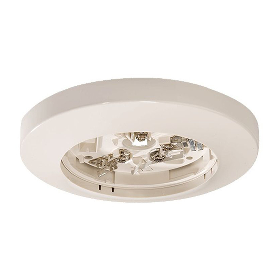
B110LP Plug-in Detector Base
For use with the following smoke detectors:
IN US:
1151, 2151
IN CANADA:
1151A, 2151A
IN EUROPE:
1151E, 2151E
Specifications
Base Diameter:
Base Height:
Weight:
Mounting:
Operating Temperature Range: 0° to 49°C (32° to 120°F)
Operating Humidity Range:
Electrical Ratings - includes base and detector
System Voltage:
Maximum Ripple Voltage:
Start-up Capacitance:
Standby Ratings:
Alarm Ratings:
Reset Voltage:
Reset Time:
Start-up Time:
Before Installing
Please thoroughly read the System Sensor manual I56-407,
Guide for Proper Use of System Smoke Detectors, which pro-
vides detailed information on detector spacing, placement,
zoning, wiring, and special applications. Copies of this
manual are available at no charge from System Sensor. (For
installation in Canada, please refer to CAN/ULC-S524,
Standard for the Installation of Fire Alarm Systems and CEC
Part 1, Sec. 32.)
NOTICE: This manual should be left with the owner/user
of this equipment.
IMPORTANT: The detector used with this base must be
tested and maintained regularly following NFPA 72 require-
ments. The detector used with this base should be cleaned
at least once a year.
D150-05-00
6.2 inches (157 mm)
0.95 inches (24 mm)
0.3 lb. (137 g)
4-inch square box with or without plaster ring. Min. depth–1.5 inches
3-1/2-inch octagon box. Min. depth–1.5 inches
10% to 93% Relative Humidity, Noncondensing
12/24 VDC
4 Volts peak-to-peak
0.02 µF Maximum
8.5 VDC Minimum
35 VDC Maximum
120 µA Maximum
4.2 VDC Minimum at 10 mA
6.6 VDC Maximum at 100 mA
(Alarm current must be limited to 100 mA (130 mA for models 1151 and 2151) by the
control panel. If it is used, the RA400Z Remote Annunciator operates within the specified
detector alarm currents.)
2.5 VDC Minimum
0.3 Seconds Minimum
34.0 Seconds Maximum
General Description
The Model B110LP detector base is designed for use with
System Sensor models 2151 photoelectronic and 1151 ion-
ization detector heads. This two-wire base is equipped with
screw terminals for the connection of power, ground, and
an optional remote annunciator.
Mounting
The detector base mounts directly to 3-1/2 inch and 4-inch
octagon boxes and 4-inch square boxes, with or without
plaster rings. To mount the base, remove the decorative
ring by rotating it in either direction to unhook the snaps
before separating the ring from the base. Use the screws
supplied with the junction box to attach the base to the box
through the appropriate slots in the base (see Figure 1).
Position the decorative ring around the base and rotate it in
either direction until the ring snaps into place.
1
3825 Ohio Avenue, St. Charles, Illinois 60174
1-800-SENSOR2, FAX: 630-377-6495
I56-594-03R
Advertisement

Subscribe to Our Youtube Channel
Related Manuals for System Sensor B110LP


Summary of Contents for System Sensor B110LP
- Page 1 Before Installing General Description Please thoroughly read the System Sensor manual I56-407, The Model B110LP detector base is designed for use with Guide for Proper Use of System Smoke Detectors, which pro- System Sensor models 2151 photoelectronic and 1151 ion- vides detailed information on detector spacing, placement, ization detector heads.
- Page 2 SNAP ON the System Sensor base and smoke detector being installed. DECORATIVE RING System Sensor smoke detectors and mounting bases are...
- Page 3 Figure 2. Wiring diagram for a typical 2-wire detector system: NOTE: IF A REMOTE ANNUN- CIATOR IS NOT USED, POLARITY OF THESE TERMINALS MAY BE REVERSED. REMOTE REMOTE ANNUNCIATOR ANNUNCIATOR A78-1175-04 CLASS A OPTIONAL WIRING To remove the detector from the base after it has been Then, insert a small screwdriver into the notch (see Figure made tamper resistant, remove the decorative ring by rotat- 3B), and press the plastic lever toward the mounting sur-...
- Page 4 NFPA 72 or at least once a year. Three-Year Limited Warranty System Sensor warrants its enclosed smoke detector base to be free from Charles, IL 60174. Please include a note describing the malfunction and defects in materials and workmanship under normal use and service for a suspected cause of failure.
Need help?
Do you have a question about the B110LP and is the answer not in the manual?
Questions and answers