Table of Contents
Advertisement
Quick Links
INSTALLATION AND MAINTENANCE INSTRUCTIONS
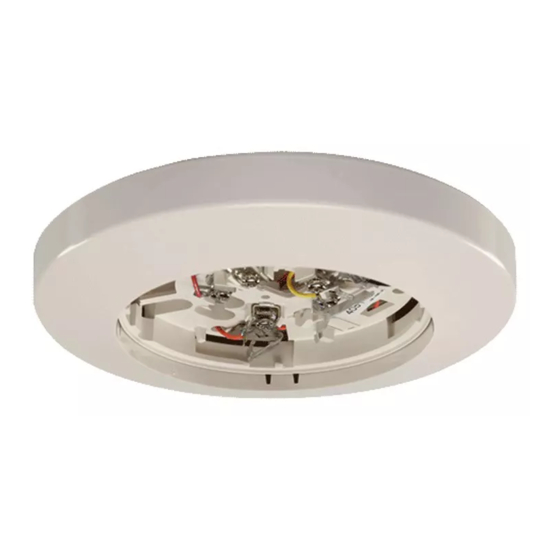
B114LP Plug-in Detector Base
For use with the following smoke detectors:
IN US:
1151, 2151
IN CANADA:
1151A, 2151A
IN EUROPE:
1151E, 2151E
Specifications
Base Diameter:
Base Height:
Weight:
Mounting:
Operating Temperature Range:
Operating Humidity Range:
Electrical Ratings - includes base and detector
System Voltage:
Relay Contact Ratings
Resistive or Inductive (60% power factor) load
Form A:
Form C:
Start-up Time:
(After 60 second reset)
Before Installing
Please thoroughly read the System Sensor manual I56-407,
Guide for Proper Use of System Smoke Detectors. This man-
ual provides detailed information on detector spacing,
placement, zoning, wiring, and special applications, and is
available at no charge from System Sensor. (For installation
in Canada, refer to CAN/ULC-S524, Standard for the
Installation of Fire Alarm Systems and CEC Part 1, Sec. 32.)
NOTICE: This manual should be left with the owner/user
of this equipment.
IMPORTANT: The detector used with this base must be
tested and maintained regularly following NFPA 72 require-
ments. The detector used with this base should be cleaned
at least once a year.
D150-02-00
6.2 inches (157 mm)
0.95 inches (24 mm)
0.6 lb. (274 g)
4-inch square box with or without plaster ring. Min. depth–1.5 inches
4-inch octagon box. Min. depth–1.5 inches
0° to 49°C (32° to 120°F)
10% to 93% Relative Humidity, Noncondensing
120 VAC, 60 Hz
2.0A @ 30VAC/DC
2.0A @ 30VAC/DC
0.6A @ 110VDC
1.0A @ 125VAC
36.0 Seconds maximum
1
General Description
The model B114LP detector base is designed for use with
System Sensor model 2151 photoelectronic and 1151 ioniza-
tion detector heads. This four-wire base is equipped with
screw terminals for the connection of power, ground, relay
connections, and an optional RA400Z remote annunciator.
It also includes a resistor that limits current when the asso-
ciated smoke detector is in the alarm state.
Mounting
The detector base mounts directly to 3-1/2 inch and 4-inch
octagon boxes and 4-inch square boxes, with or without
plaster rings. To mount the base, remove the decorative
ring by rotating it in either direction to unhook the snaps
before separating the ring from the base. Use the screws
supplied with the junction box to attach the base to the box
through the appropriate slots in the base.
See Figure 2. Position the decorative ring around the base
and rotate it in either direction until the ring snaps into
place.
3825 Ohio Avenue
St. Charles, Illinois 60174
1-800-SENSOR2, FAX: 630-377-6495
I56-598-03R
Advertisement
Table of Contents

Related Manuals for System Sensor B114LP


Summary of Contents for System Sensor B114LP
- Page 1 Before Installing General Description Please thoroughly read the System Sensor manual I56-407, The model B114LP detector base is designed for use with Guide for Proper Use of System Smoke Detectors. This man- System Sensor model 2151 photoelectronic and 1151 ioniza- ual provides detailed information on detector spacing, tion detector heads.
- Page 2 DECORATIVE specification to ensure that it is listed as compatible with RING the System Sensor base and smoke detector being installed. All wiring must be installed in compliance with the SCREWS (NOT National Electrical Code and all applicable local codes and...
- Page 3 NOTE: Do NOT use the tamper-resistance feature if the built-in shorting spring makes it convenient to do this. System Sensor XR2 Removal Tool will be used to After the detector base is wired and attached to the electri- remove detectors from the base.
- Page 4 Please refer to insert for the Limitations of Fire Alarm Systems Three-Year Limited Warranty System Sensor warrants its enclosed smoke detector base to be free from Charles, IL 60174. Please include a note describing the malfunction and defects in materials and workmanship under normal use and service for a suspected cause of failure.
Need help?
Do you have a question about the B114LP and is the answer not in the manual?
Questions and answers