Advertisement
INSTALLATION AND MAINTENANCE INSTRUCTIONS
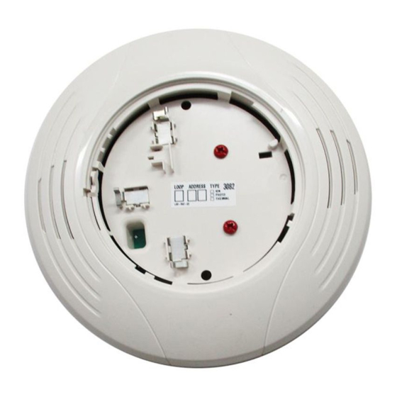
B224BI-WH, B224BI-IV
Plug-in Isolator Detector Base
SPECIFICATIONS
Base Diameter:
Base Height:
Operating Temperature Range:
Operating Humidity Range:
Electrical Ratings
Operating Voltage:
Standby Current:
Isolation Current:
BEFORE INSTALLING
Please read the System Smoke Detector Applications Guide, which provides
detailed information on detector spacing, placement, zoning, wiring, and spe-
cial applications. This manual is available online at www.systemsensor.com.
NFPA 72 guidelines should be observed.
NOTICE: This manual should be left with the owner/user of this equipment.
IMPORTANT: The detectors used with these bases must be tested and main-
tained following NFPA 72 requirements. The detectors used with these bases
should be cleaned at least once a year.
GENERAL INFORMATION
The B224BI-WH and B224BI-IV isolator bases intended for use in an intelli-
gent system. Isolator bases prevent an entire communications loop from being
disabled when a short circuit occurs. They accomplish this by isolating that
part of the loop containing the short from the remainder of the circuit. These
bases also automatically restore the entire loop when the cause of the short
circuit is corrected. In general, up to 25 addressable devices may be isolated
between isolator bases.
MOUNTING
Mount the mounting plate directly to an electrical box. The plate will
mount directly to 4" square (with and without plaster ring), 4" octagon,
1
3
/
" octagon, single gang and double gang junction boxes.
2
1. Connect field wiring to terminals, as shown in Figure 3 and 4.
2. Attach the mounting plate to the junction box as shown in Figure 2.
3. To mount the base, hook the tab on the base to the groove on the mounting plate.
FIGURE 1.
TERMINAL DESIGNATION
1
2
3
C0471-05
B224BI-WH/B224BI-IV
TERMINALS
No. Function
1.
Positive (+) Comm. Line In
2.
Negative (–) Comm. Line In
and Out
3.
Positive (+) Comm. Line Out
6.85 in (17.4 cm)
1.61 in (4.1 cm)
Refer to applicable sensor Operating Temperature Range using the Base/Sensor Cross Reference Chart at systemsensor.com
10% to 93% Relative Humidity (Non-condensing)
15 to 32 VDC
450 µA Maximum
15 mA Maximum
FIGURE 2. MOUNTING BASE TO
ELECTRICAL BOX
SCREWS
(NOT SUPPLIED)
MOUNTING
PLATE
BOX
(NOT SUPPLIED)
4. Then, swing the base into position to engage the pins on the product with
the terminals on the mounting plate.
5. Secure the base by tightening the mounting screws.
6. Install a compatible smoke detector as described in the installation manual
for the detector.
Do not over tighten mounting plate screws; this may cause mounting plate
to flex.
INSTALLATION GUIDELINES
All wiring must be installed in compliance with all applicable local codes and
any special requirements of the local authority having jurisdiction, using the
proper wire sizes. The conductors used to connect smoke detectors to control
panels and accessory devices should be color-coded to reduce the likelihood
of wiring errors. Improper connections can prevent a system from responding
properly in the event of a fire.
For signal wiring (the wiring between interconnected detectors), it is recom-
mended that the wire be no smaller than 18 AWG (0.823 mm
sizes up to 12 AWG (3.31 mm
Alarm system control panels have specifications for allowable loop resistance.
Consult the control panel specifications for the total loop resistance allowed
before wiring the detector loops.
Check the zone wiring of all bases in the system before installing detectors.
This includes checking the wiring for continuity, correct polarity, ground fault
testing, and performing a dielectric test.
FIGURE 3.
1 - COMM IN (+)
2 - COMM IN (–)
CLASS A OPTIONAL WIRING
C1008-01
1
3825 Ohio Avenue, St. Charles, Illinois 60174
1.800.SENSOR2; Fax: 630.377.6495
www.systemsensor.com
CAUTION
2
). However, wire
2
) can be used with the base.
3 - COMM OUT (+)
(+)
2 - COMM OUT (–)
(–)
OTHER
INTELLIGENT
DEVICES
(+)
(–)
C1003-01
I56-3736-005
02/01/2018
Advertisement
Table of Contents

Related Manuals for System Sensor B224BI-WH


Summary of Contents for System Sensor B224BI-WH
- Page 1 GENERAL INFORMATION INSTALLATION GUIDELINES The B224BI-WH and B224BI-IV isolator bases intended for use in an intelli- All wiring must be installed in compliance with all applicable local codes and gent system. Isolator bases prevent an entire communications loop from being any special requirements of the local authority having jurisdiction, using the disabled when a short circuit occurs.
- Page 2 Please refer to insert for the Limitations of Fire Alarm Systems THREE-YEAR LIMITED WARRANTY System Sensor warrants its enclosed smoke detector base to be free from defects in ma- Drive, Suite 700, El Paso TX 79936, USA. Please include a note describing the malfunc- terials and workmanship under normal use and service for a period of three years from tion and suspected cause of failure.
Need help?
Do you have a question about the B224BI-WH and is the answer not in the manual?
Questions and answers