System Sensor WFD Series Installation And Maintenance Instructions Manual
Vane-type waterflow detectors
Hide thumbs
Also See for WFD Series:
- Installation and maintenance instructions (4 pages) ,
- Installation and maintenance instructions (4 pages)
Table of Contents
Advertisement
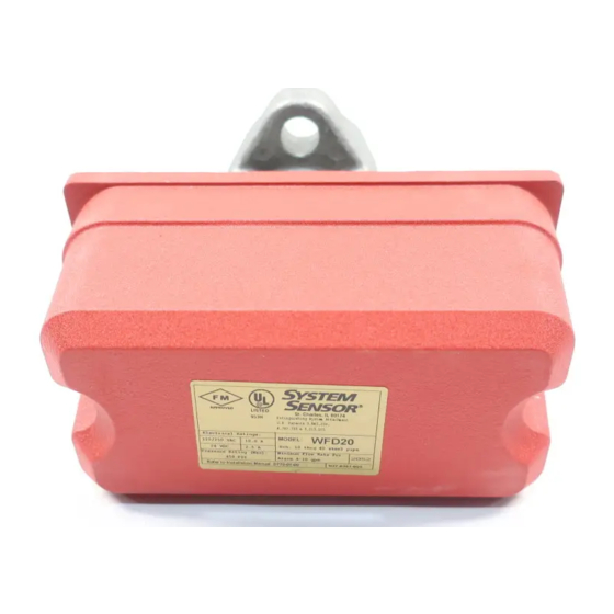
WFD Vane-type Waterflow
Detectors
Specifications
Triggering Threshold Bandwidth (Flow Rate): 4 to 10 gpm
Static Pressure Rating:
Dimensions, Installed:
Operating Temperature Range:
Compatible Pipe:
Shipping Weight:
Enclosure Rating:
(requires optional Outdoor Cover Gasket Model WFDN4 and cover part #C58-164-01)
Important
Please Read Carefully And Save
This instruction manual contains important information
about the installation and operation of waterflow detectors.
Purchasers who install waterflow detectors for use by oth-
ers must leave this manual or a copy of it with the user.
Read all instructions carefully before beginning. Follow
only those instructions that apply to the model you are in-
stalling.
Use vane-type waterflow detectors in wet-pipe systems
only. Do NOT use them in dry pipe, deluge, or preaction
systems. The sudden inrush of water in such systems may
break the vane or damage the mechanism.
Do not use in potentially explosive atmospheres. Do not al-
low unused wires to remain exposed.
D770-01-00
Technical Manuals Online! - http://www.tech-man.com
10 A @ 125/250 VAC
2.5 A @ 24 VDC
250 PSI (Max) 2" – 8"
3.5"H x 3.0"W x 6.7"D
32° F to 120° F (0°C to 49°C)
Steel water pipe, schedule 10 or 40.
4 to 7 lb., according to size.
NEMA 4, as tested by Underwriters Laboratories, Inc.
CAUTION
3825 Ohio Avenue, St. Charles, Illinois 60174
Principles Of Operation
Vane-type waterflow detectors mount to water-filled pipes
in sprinkler systems. Waterflow in the pipe deflects a vane,
which produces a switched output–usually after a specified
delay. All waterflow detectors have a pneumatically con-
trolled mechanical delay mechanism. Delays do NOT accu-
mulate; they reset if the flow of water stops before the
entire delay has elapsed. All switches actuate when the wa-
ter flow rate is 10 gallons per minute or greater, but will not
actuate if the flow rate is less than 4 gallons per minute.
This System Sensor installation manual covers the follow-
ing waterflow detectors for sprinkler/fire alarm applica-
tions.
Models
WFD20
Waterflow detector, Schedule 10/40, 2"
WFD25
Waterflow detector, Schedule 10/40, 2-1/2"
WFD30
Waterflow detector, Schedule 10/40, 3"
WFD35
Waterflow detector, Schedule 10/40, 3-1/2"
WFD40
Waterflow detector. Schedule 10/40, 4"
WFD50
Waterflow detector, Schedule 10/40, 5"
WFD60
Waterflow detector, Schedule 10/40, 6"
WFD80
Waterflow detector, Schedule 10/40, 8"
1
A Division of Pittway
1-800-SENSOR2, FAX: 630-377-6495
I56-459-07
Advertisement
Table of Contents

Related Manuals for System Sensor WFD Series


Summary of Contents for System Sensor WFD Series
- Page 1 10 gallons per minute or greater, but will not stalling. actuate if the flow rate is less than 4 gallons per minute. This System Sensor installation manual covers the follow- CAUTION ing waterflow detectors for sprinkler/fire alarm applica- Use vane-type waterflow detectors in wet-pipe systems tions.
- Page 2 Failure to follow these directions may prevent the device A78-1609-00 from reporting the flow of water in the event the associated sprinkler system is activated by a fire. System Sensor is not responsible for devices that have been improperly installed, tested, or maintained.
- Page 3 Table 1: Table 2: WFD SIZE Hole Size WFD SIZE Torque 2 " - 3-1/2 " 1-1/4 " 2 " - 3-1/2 " 30 - 35 ft-lb 4 " - 8 " 2 " 4 " - 8 " 55 - 60 ft-lb CAUTION When drilling the hole with a hole saw, make certain that the center of the cut does not remain in the pipe.
- Page 4 Figure 3. Assembly diagram: Cover Tamper proof wrench (P/N WFDW) Switch enclosure (Replacement P/N A77-01-02) Delay mechanism Conduit entrance (Replacement P/N A3008-00) Direction-of-flow arrow Mounting plate U-bolt nut Pipe saddle Plastic vane Roll paddle opposite of flow arrow while inserting Saddle gasket Pipe WFD Size...
- Page 5 Figure 4. WFD wiring: WFD Switch Assembly Top View NOTE: Common and B connections will close when vane is deflected, i.e., Switch 1 when water is flowing. Dual switches permit applications to be combined on a single detector. CONTACT RATINGS Switch 2 125/250 VAC 10 AMPS...
- Page 6 After extended service, parts of the detector may become Under normal conditions, System Sensor waterflow detec- worn, reducing the delay time and causing false alarms. If tors should provide years of trouble-free service. However, this happens, increase the delay.
- Page 7 To remove a detector: 1. Drain the pipe. 2. Turn off electrical power to the detector and disconnect the wiring. 3. Loosen the nuts and remove the U-bolts. 4. Gently lift the saddle far enough to get your fingers un- der it.
- Page 8 Three-Year Limited Warranty System Sensor warrants its enclosed waterflow detector to be free from de- Repair Department, RA #__________, 3825 Ohio Avenue, St. Charles, IL fects in materials and workmanship under normal use and service for a 60174.
- Page 9 INSTALLATION AND MAINTENANCE INSTRUCTIONS WFDT/WFDTH Vane-type A Division of Pittway 3825 Ohio Avenue, St. Charles, Illinois 60174 Waterflow Detectors 1-800-SENSOR2, FAX: 630-377-6495 Specifications Contact Ratings: Two sets of SPDT (Form C) 10 A @ 125/250 VAC; 2.5 A @ 24 VDC Triggering Threshold Bandwidth (Flow Rate): 4 - 10 GPM Service Pressure Rating:...
- Page 10 Failure to follow these directions may result in failure of the Be sure the direction-of-flow arrow points in the right direc- device to report a waterflow condition. System Sensor is tion, otherwise a waterflow condition will go unreported. not responsible for devices that have been improperly See Figure 2.
- Page 11 Figure 3. Field wiring: Top View NOTE: Common and B connections will close when vane is deflected, i.e., Switch 1 when water is flowing. Dual switches permit applications to be combined on a single detector. CONTACT RATINGS Switch 2 125/250 VAC 10 AMPS 24 VDC 2.5 AMPS...
- Page 12 Three-Year Limited Warranty System Sensor warrants its enclosed waterflow detector to be free from de- Repair Department, RA #__________, 3825 Ohio Avenue, St. Charles, IL fects in materials and workmanship under normal use and service for a 60174.
- Page 13 NFPA 72: Installation, Maintenance and Use of Local Failure to follow these directions may result in failure of the Protective Signalling Systems device to report a waterflow condition. System Sensor is N770-06-00 I56-509-01 Technical Manuals Online! - http://www.tech-man.com...
- Page 14 Figure 2. Assembly diagram: wrench. Use of thread sealant or tape is recommended. Use height gage (located at end of paddle tee) to ensure proper depth of detector on tee fitting. See Figure 1. COVER Height gage must fit between top of tee fitting and under side of hex tee adapter.
- Page 15 Typical Local Bell Connection 3. A ground screw is provided with all WFDT units. When Under normal conditions System Sensor waterflow detec- grounding is required, clamp wire with screw in hole lo- tors should provide years of trouble-free service. If, how- cated between conduit entrance holes.
- Page 16 Three-Year Limited Warranty System Sensor warrants its enclosed waterflow detector to be free from de- Repair Department, RA #__________, 3825 Ohio Avenue, St. Charles, IL fects in materials and workmanship under normal use and service for a 60174.
- Page 17 Please Read Carefully And Save This manual contains important information about the in- stallation and operation of supervisory switches. These in- structions apply to System Sensor switches for outside screw and yoke valves only. Read all instructions carefully before beginning installation.
- Page 18 Figure 2: Wrench for Cover tamper-resistant screws Tamper-resistant (P/N WFDW) screws Spring Actuating Cam Mounting screws Actuating lever set screw Terminal block Seal Base housing Mounting Bracket "C" clip Actuating lever roller (2 thru 12"only) Valve Stem Carriage Bolt Yoke Clamping Bar Hex wrench Retaining Washer...
- Page 19 the valve, slide the open end of the clamping bar onto Figure 3: the bolts and under the retaining washers, as indicated in Figure 2. THREADED VALVE STEM HEX VALVE 7. Ensure that the actuating lever does not hit the inside YOKE STEM of the cover or the clamping bar at any point in its...
- Page 20 60174. Please include a note describing the malfunction and suspected period of three years from date of manufacture. System Sensor makes no cause of failure. The Company shall not be obligated to repair or replace other express warranty for this supervisory switch.
- Page 21 Purchasers who install supervisory switches for use by oth- Cover ers must leave this manual or a copy of it with the user. These instructions apply to System Sensor switches for post Tamper screws indicator and butterfly type valves. Read all instructions 4-1/4"...
- Page 22 Figures 2A and 2B: location. Drill with a " drill bit and tap a " NPT thread. Falling flag Rising Flag 5. Replace the head and target assembly. 6. Screw the locknut onto the threaded nipple which is supplied with the PIBV2. 7.
- Page 23 Figure 3: Actuator Vertical (Pointing Up) 2. Ground Screw — A ground screw is provided with all supervisory switch models. When grounding is required, clamp wire with the screw in hole located near conduit entrance. A78-1633-00 3. Wiring — See Figure 6, Page 4. nipple, orienting the PIBV2 to trip the switch as the Section 4 valve closes.
- Page 24 60174. Please include a note describing the malfunction and suspected period of three years from date of manufacture. System Sensor makes no cause of failure. The Company shall not be obligated to repair or replace other express warranty for this supervisory switch.
- Page 25 General Information device to report an alarm or trouble condition. System Sen- This cover tamper switch mounts to all System Sensor sor is not responsible for devices that have been improperly WFD, WFDT, OSY2 and PIBV2 terminal block units. Cover installed, tested or maintained.
- Page 26 2) Verify that circuit has reset by checking FACP. Three-Year Limited Warranty System Sensor warrants its enclosed cover tamper switch to be free from Repair Department, RA #__________, 3825 Ohio Avenue, St. Charles, IL defects in materials and workmanship under normal use and service for a 60174.
- Page 27 General Information 4. Wire the circuit as shown in Figures 2, 3, or 4, or as re- The System Sensor 546-8000 cover tamper switch mounts quired by the installation requirements and as approved to EPS series pressure switches to monitor removal of the by the authority having jurisdiction.
- Page 28 PANEL A78-2619-00 Three-Year Limited Warranty System Sensor warrants its enclosed cover tamper switch to be free from Repair Department, RA #__________, 3825 Ohio Avenue, St. Charles, IL defects in materials and workmanship under normal use and service for a 60174. Please include a note describing the malfunction and suspected period of three years from date of manufacture.
- Page 29 Failure to follow these directions may result in failure of the SWITCH #1 ADJUSTMENT GROUND device to report an alarm condition. System Sensor is not SCREW SCREW (GREEN) responsible for devices that have been improperly installed, tested, or maintained.
- Page 30 Figure 2. Typical piping diagram for EPS10-1, EPS10-2 WIRE TO ALARM WIRE TO ALARM WIRE TO ALARM INDICATING CIRCUIT INDICATING CIRCUIT INDICATING CIRCUIT OF FIRE ALARM EPS10 OF FIRE ALARM EPS10 OF FIRE ALARM EPS10 CONTROL PANEL CONTROL PANEL CONTROL PANEL WATER SPRINKLER SPRINKLER...
- Page 31 If you have factory to alarm at 4–8 PSI on rising pressure (see Table 2). any questions, consult System Sensor. System Sen- Pressure switch settings may be adjusted in the field to ob- sor recommends careful consideration of the fol-...
- Page 32 Three-Year Limited Warranty System Sensor warrants its enclosed pressure switch to be free from de- ment, RA #__________, 3825 Ohio Avenue, St. Charles, IL 60174. Please fects in materials and workmanship under normal use and service for a include a note describing the malfunction and suspected cause of failure.
- Page 33 MAIN ADJUSTMENT Failure to follow these directions may result in failure of the WHEEL LOCKING SCREW device to report an alarm condition. System Sensor is not responsible for devices that have been improperly installed, tested, or maintained. 1/2" NPT A78-2345-00...
- Page 34 Figure 2. Typical piping diagram for EPS40-1, Figure 3. Typical piping diagram for EPS120-1, EPS40-2 EPS120-2 WIRE TO SUPERVISORY WIRE TO ALARM EPS120 INDICATING CIRCUIT CIRCUIT OF FIRE ALARM CONTROL PANEL OF FIRE ALARM PRESSURE EPS40 EPS10 CONTROL PANEL SUPPLY SPRINKLER SYSTEM WATER...
- Page 35 If you have until switch trip point is at desired pressure setting. The any questions, consult System Sensor. System Sen- approximate sensitivity of the adjustment wheel: 1/2 sor recommends careful consideration of the fol- turn = 11 PSI for the EPS40-1;...
- Page 36 • Avoid impact or mechanical loading. Three-Year Limited Warranty System Sensor warrants its enclosed pressure switch to be free from de- ment, RA #__________, 3825 Ohio Avenue, St. Charles, IL 60174. Please fects in materials and workmanship under normal use and service for a include a note describing the malfunction and suspected cause of failure.
- Page 37 Three-Year Limited Warranty System Sensor warrants its enclosed pressure switch to be free from de- ment, RA #__________, 3825 Ohio Avenue, St. Charles, IL 60174. Please fects in materials and workmanship under normal use and service for a include a note describing the malfunction and suspected cause of failure.
- Page 38 These bells are intended to be connected to alarm indicat- ing circuits of UL listed fire alarm control panels. The SSM These instructions apply to all System Sensor bells in the series is polarized to enable supervision of the installation series.
- Page 39 In this case, bell should be replaced. Failure to follow these directions may result in failure of the device to report an alarm condition. System Sensor is not Do not repair or replace any bell components in the responsible for devices that have been improperly installed, field.
- Page 40 Figure 1. Typical SSM and SSV bell wiring diagrams: WIRING (REAR VIEW) USE BOTH LEADS FOR USE BOTH LEADS FOR OBSERVE POLARITY CONNECTION. BREAK CONNECTION. BREAK ON SSMA MODELS WIRE RUN TO PROVIDE WIRE RUN TO PROVIDE ELECTRICAL SUPERVISION. ELECTRICAL SUPERVISION. BLACK BLACK BLACK...
- Page 41 Three-Year Limited Warranty System Sensor warrants its enclosed SSM or SSV bell to be free from de- ment, RA #__________, 3825 Ohio Avenue, St. Charles, IL 60174. Please fects in materials and workmanship under normal use and service for a include a note describing the malfunction and suspected cause of failure.
Need help?
Do you have a question about the WFD Series and is the answer not in the manual?
Questions and answers