Table of Contents
Advertisement
INSTALLATION AND MAINTENANCE INSTRUCTIONS
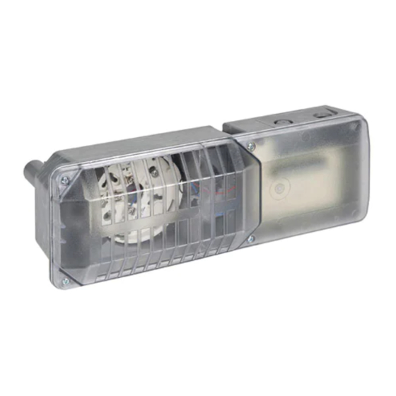
DH400 Air Duct Smoke Detector
Before Installing
Please thoroughly read System Sensor's Guide for Proper
Use of Smoke Detectors in Duct Applications (I56-473-XX),
which provides detailed information on detector spacing,
placement, zoning, wiring, and special applications. Copies
of this manual are available from System Sensor. NFPA
Standards 72 and 90A should also be referenced for de-
tailed information.
NOTICE: This manual should be left with the owner/user
of this equipment.
IMPORTANT: This detector must be tested and maintained
regularly following NFPA 72 requirements. The detector
should be cleaned at least once a year.
Table of Contents
[1] General Description
List Of Tables And Figures
Fig. 1: Duct Detector Exploded View
Fig. 2: Installation of Sampling Tube Gaskets
Fig. 3: Mounting Location of Speed Nuts
Table 1: Inlet Sampling Tube Selection
Fig. 4: Inlet Sampling Tube
Fig. 5: Sampling Tube Mounting Configurations
Fig. 6: System Wiring Diagram (2-wire)
Fig. 7: Wiring Diagram for Remote Test Station
Fig. 8: Sampling Tube Filter Installation
Fig. 9: Testing Detector Alarm
Fig. 10: Detector Head Removal
Fig. 11: RTS451/RTS451KEY Test Coil Installation
Fig. 12: Photo Head Exploded View
Fig. 13: Ion Head Exploded View
D400-14-00
[1] General Description
An HVAC system supplies conditioned air to virtually every
area of a building. Smoke introduced into this air duct sys-
tem will be distributed to the entire building. Smoke detec-
tors designed for use in air duct systems are used to sense
the presence of smoke in the duct.
Model DH400 Air Duct Smoke Detectors are supplied with
System Sensor's model 1451DH ionization detector heads
or model 2451 photoelectronic detector heads. These two
principle smoke detection methods are combined with an
efficient housing design that samples air passing through a
duct and allows detection of a developing hazardous condi-
tion. When sufficient smoke is sensed, an alarm signal is
initiated at the fire control panel monitoring the detector,
and appropriate action can be taken to shut off fans, blow-
Page
ers, change over air handling systems, etc. These actions
1
can facilitate the management of toxic smoke and fire gases
2
throughout the areas served by the duct system.
2
2
DH400 detectors are designed to operate with 12 or 24 VDC
2
UL listed compatible 2-wire control panels. Alarm current
8
must be limited to 100mA or less by the control panel. Aux-
10
iliary relay contacts for control purposes are not available
12
for use with the DH400. Control must initiate from the con-
13
trol panel.
16
For testing, the alarm can be enabled by a magnet activated
Page
test switch, by insertion of a calibrated test card into the sens-
2
ing chamber (photoelectronic version only), or by the op-
3
tional remote test station. The duct smoke detectors latch into
3
alarm state when alarm occurs. LEDs on each detector illumi-
3
nate to provide local alarm indication, and the optional
4
RA400Z accessory offers remote LED annunciation capability.
4
The DH400 duct detector must be reset by the control panel.
6
7
8
9
9
10
11
11
1
A Division of Pittway
3825 Ohio Avenue, St. Charles, Illinois 60174
1-800-SENSOR2, FAX: 630-377-6495
I56-554-05
Advertisement
Table of Contents

Related Manuals for System Sensor DH400


Summary of Contents for System Sensor DH400
-
Page 1: Table Of Contents
[3] Contents of the Duct Detector Kit [4] Limitations of Duct Detectors DH400 detectors are designed to operate with 12 or 24 VDC [5] Installation Sequence UL listed compatible 2-wire control panels. Alarm current [6] Duct Detector Maintenance and Test Procedures must be limited to 100mA or less by the control panel. -
Page 2: Exploded View Of Duct Detector Components
[5.1] Verify Duct Air Flow Direction And Velocity means of providing life safety. Nor are they a substitute for Model DH400 detectors are designed to be used in air han- early warning in a building’s regular fire detection system. dling systems having air velocities of 500 to 4000 feet per minute. - Page 3 [5.2] Drill The Mounting Holes [5.4] Install The Inlet Remove the paper backing from the mounting template The inlet tube (shown in Figure 4) is identified by a series supplied. Affix the template to the duct at the desired of air inlet holes on the tube. This tube must be purchased mounting location.
- Page 4 Figure 4. Air duct detector inlet sampling tube: AIR HOLES INLET FLANGE TUBE PLUG ARROWS AIR FLOW DIRECTION MUST FACE INTO AIR FLOW A78-2047-00 Figure 5. Tube mounting configurations with varying air flow direction: DOTS INDICATE POSITION OF SAMPLING TUBE HOLES AIR FLOW AIR FLOW DIRECTION...
- Page 5 1 inch to 1-1/4 inch hole where the flange will be used. DH400 detectors are designed to operate with 12 or 24 VDC UL listed 2-wire compatible control panels. Alarm current [5.4.3] Modifications of Inlet Sampling Tubes must be limited by the control panel to 100mA or less.
- Page 6 UL LISTED 1ST DETECTOR LAST DETECTOR COMPATIBLE 2-WIRE IN LOOP DH400 IN LOOP DH400 CONTROL PANEL EOL RESISTOR SUPERVISORY SUPERVISORY SPECIFIED BY SWITCH SWITCH PANEL MANUFACTURER (+) IN (+) OUT (+) IN (+) OUT RA400Z (OPTIONAL) RA400Z (OPTIONAL) REMOTE ALARM LED...
- Page 7 MAGNET SUPPLIED TEST (–) BY USER SWITCH (100mA SUPPLY) RTS451/RTS451KEY (OPTIONAL) DH400 24 VAC (+10%, –15%) REMOTE TEST STATION DUCT DETECTOR FULL WAVE RECTIFIED, UNFILTERED POWER MAY BE USED METHOD #1 — AUX POWER LOCATED AT DUCT DETECTOR 2.8 VDC...
-
Page 8: Duct Detector Maintenance And Test Procedures
See Section [6] for TION PROPERLY. more information. Replacement filters can be ordered from System Sensor, 3825 Ohio Ave., St. Charles, IL 60174. (Ex- haust tube/intake tube filter P/N F36-05-00) [5.7] Perform Detector Check 1. - Page 9 In no case should the pressure differen- of the alarm capability of the duct detector as indicated in tial fall below 0.01 inches of water. the RTS451/RTS451KEY manual. The DH400 duct detector must be reset by the system control panel. [6.2] Standby, Alarm, And Sensitivity Tests To install the RTS451/RTS451KEY, connect the device as [6.2.1] Standby And Trouble...
-
Page 10: Detector Cleaning Procedures
Figure 11. RTS451/RTS451KEY test coil installation: TEST COIL DETECTOR HEAD A78-1994-02 [6.2.3] Sensitivity Tests 7. Put the cover back by gently rotating it clockwise until it [6.2.3.1] MOD400 or MOD400R Test locks in place. Secure the duct housing cover using the 4 After verification of alarm capability, the MOD400 or cover screws. - Page 11 Figure 12. Photo head exploded view: Figure 13. Ion head exploded view: REMOVABLE HEAD COVER REMOVABLE COVER CLEANING TEST SLOT REMOVABLE SCREEN (P/N RS14) CLEANABLE SCREEN P/N RS24 (W/O THERMAL) LOCK PRONG SENSING CHAMBER HEAD COVER REMOVAL SLOT VANED CHAMBER A78-1213-01 A78-2340-00 [7.3] Ion Heads...
-
Page 12: Specifications
[8] Model Dh400 Air Duct Smoke Detector Specifications Description HVAC air duct mounted ionization or photoelectronic smoke detector for 2-wire alarm systems. Environmental Limits Temperature: 32° to 120° F 0° to 49° C Humidity: 10% to 93% R.H. non-condensing Air Velocity: 500 to 4000 ft./min. -
Page 13: Warranty
St. Charles, IL 60174. Please include a note describing the malfunction and for a period of three years from date of manufacture. System Sensor makes suspected cause of failure. The Company shall not be obligated to repair no other express warranty for this air duct smoke detector. - Page 14 NOTES D400-14-00 I56-554-05...
- Page 15 NOTES D400-14-00 I56-554-05...
-
Page 16: Detector Test Log
____________ ________ _______________ _____________________________ ________ ____________ ________ _______________ _____________________________ ________ ____________ ________ _______________ _____________________________ ________ ____________ ________ _______________ _____________________________ ________ ____________ ________ _______________ _____________________________ ________ ____________ ________ _______________ _____________________________ ________ ____________ ________ _______________ _____________________________ D400-14-00 I56-554-05 © System Sensor 1996...
Need help?
Do you have a question about the DH400 and is the answer not in the manual?
Questions and answers