System Sensor WFD Series Installation And Maintenance Instructions
Vane-type waterflow detectors
Hide thumbs
Also See for WFD Series:
Table of Contents
Advertisement
Quick Links
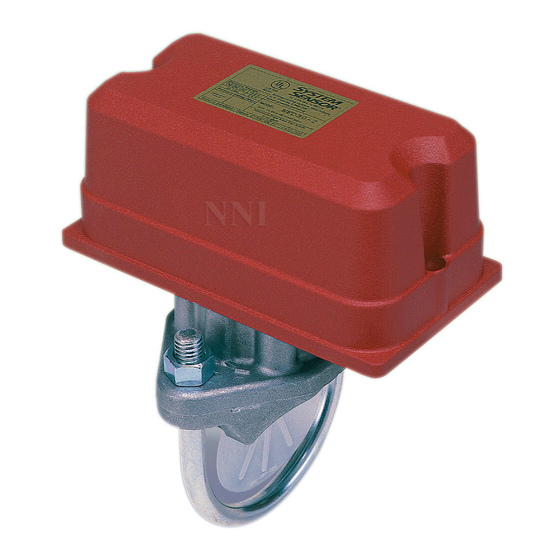
INSTALLATION AND MAINTENANCE INSTRUCTIONS
WFD Vane-type Waterflow
Detectors
Specifications
Contact Ratings:
Triggering Threshold Bandwidth (Flow Rate):
Static Pressure Rating:
Dimensions, Installed:
Operating Temperature Range:
Compatible Pipe:
Shipping Weight:
Enclosure Rating:
Important
Please Read Carefully And Save
This instruction manual contains important information about the instal-
lation and operation of waterflow detectors. Purchasers who install
waterflow detectors for use by others must leave this manual or a copy of
it with the user.
Read all instructions carefully before beginning. Follow only those instruc-
tions that apply to the model you are installing.
Use vane-type waterflow detectors in wet-pipe systems only. Do NOT use
them in dry pipe, deluge, or preaction systems. The sudden inrush of wa-
ter in such systems may break the vane or damage the mechanism.
Do not use in potentially explosive atmospheres. Do not allow unused
wires to remain exposed.
Principles Of Operation
Vane-type waterflow detectors mount to water-filled pipes in sprinkler sys-
tems. Waterflow in the pipe deflects a vane, which produces a switched
output–usually after a specified delay. All waterflow detectors have a
pneumatically controlled mechanical delay mechanism. Delays do NOT
accumulate; they reset if the flow of water stops before the entire delay
has elapsed. All switches actuate when the water flow rate is 10 gallons
per minute or greater, but will not actuate if the flow rate is less than 4
gallons per minute. This System Sensor installation manual covers the fol-
lowing waterflow detectors for sprinkler/fire alarm applications.
Models
WFD20
Waterflow detector, Schedule 10/40, 2"
WFD25
Waterflow detector, Schedule 10/40, 2-1/2"
WFD30
Waterflow detector, Schedule 10/40, 3"
WFD30-2 Waterflow detector, Schedule 10/40, 3" (U.L. Listed only)
WFD35
Waterflow detector, Schedule 10/40, 3-1/2"
WFD40
Waterflow detector. Schedule 10/40, 4"
WFD50
Waterflow detector, Schedule 10/40, 5"
WFD60
Waterflow detector, Schedule 10/40, 6"
WFD80
Waterflow detector, Schedule 10/40, 8"
Do NOT use any of the WFD models on copper pipe. The clamping forces
of the mounting bolts may collapse the pipe sufficiently to prevent the de-
tector from functioning properly.
Do NOT install steel or iron pipe sections in copper piping for mounting a
waterflow detector. Incompatibility between the dissimilar metals causes
bimetallic corrosion.
D770-01-00
Technical Manuals Online! - http://www.tech-man.com
10 A @ 125/250 VAC; 2.5 A @ 24 VDC
4 to 10 gpm
450 PSI (Max) 2" – 8", as tested by Underwriters Laboratories (U.L.)
250 PSI (Max) 2" – 8", as tested by Factory Mutual.
3.5"H x 3.0"W x 6.7"D
32° F to 120° F (0° C to 49° C)
Steel water pipe, schedule 10 or 40.
4 to 7 lb., according to size.
NEMA Type 4, as tested by Underwriters Laboratories, Inc.
CAUTION
CAUTION
3825 Ohio Avenue, St. Charles, Illinois 60174
Installation Guidelines
Before installing any waterflow alarm device, be thoroughly familiar with:
NFPA 72:
National Fire Alarm Code
NFPA 13:
Installation of Sprinkler Systems, Section 3.17
NFPA 25:
Inspection, Testing and Maintenance of Sprinkler Systems
Other applicable NFPA standards, local codes, and the requirements of the
authority having jurisdiction
Failure to follow these directions may prevent the device from reporting
the flow of water in the event the associated sprinkler system is activated
by a fire. System Sensor is not responsible for devices that have been im-
properly installed, tested, or maintained.
1. Mount the detector where there is adequate clearance for installation
and removal and a clear view of it for inspections. See Figure 1 for
mounting dimensions.
2. Locate to protect from damage – 6 to 7 feet above the floor.
3. On horizontal runs, position the detector on the top or side of the pipe.
Do not mount it upside down because condensation may collect in the
housing and impair the operation of the detector. For vertical flow ap-
plications, mount the detector on pipe through which water flows up-
ward. Otherwise, the unit may not operate properly.
4. Mount the detector at least 6 inches from a fitting that changes the di-
rection of water flow and no less than 24 inches from a valve or drain.
5. Be sure the direction-of-flow arrow matches the direction of flow
in the pipe.
Mounting Instructions
1. Drain the pipe.
2. Cut a hole at the desired location. Center the hole in the pipe, as
shown in Figure 2, and be sure the hole is perpendicular to the center
of the pipe. Before drilling, use a punch or scribe to mark the drill site
to prevent the bit from slipping. If the hole is off center, the vane will
bind against the inside wall of the pipe. Use a drill or hole saw to cut a
hole of the proper diameter. See Table 1 for hole size.
When drilling the hole with a hole saw, make certain that the center of the
cut does not remain in the pipe.
3. Remove burrs and sharp edges from the hole. Clean and remove
all scale and foreign matter from the inside of the pipe for one di-
ameter on each side of the hole to ensure free movement of the
vane. Clean the outside of the pipe to remove dirt, metal chips,
and cutting lubricant.
4. Seat the O-ring or gasket against the saddle and mount the detector di-
rectly to the pipe. Carefully roll the vane opposite the direction of flow
and insert it through the hole. Seat the saddle firmly against the pipe
1
A Division of Pittway
1-800-SENSOR2, FAX: 630-377-6495
CAUTION
I56-459-11
Advertisement
Table of Contents

Related Manuals for System Sensor WFD Series


Summary of Contents for System Sensor WFD Series
- Page 1 Failure to follow these directions may prevent the device from reporting the flow of water in the event the associated sprinkler system is activated by a fire. System Sensor is not responsible for devices that have been im- CAUTION properly installed, tested, or maintained.
- Page 2 so that the locating boss goes into the hole. Figure 1. Mounting dimensions: 5. Install the U-bolt, tightening the nuts alternately to ensure a uniform 3-3/4" seal. See Table 2 for torque values. 6. Remove the metal cover with the tamper-proof wrench provided. Move the actuator lever back and forth to check for binding.
- Page 3 Pipe saddle having jurisdiction. Plastic vane Under normal conditions, System Sensor waterflow detectors should pro- vide years of trouble-free service. However, if the delay mechanism or switch enclosure becomes faulty, replace it. To replace the delay mecha- Roll paddle opposite ″...
- Page 4 4 or 5 years. Three-Year Limited Warranty System Sensor warrants its enclosed waterflow detector to be free from de- Repair Department, RA #__________, 3825 Ohio Avenue, St. Charles, IL fects in materials and workmanship under normal use and service for a 60174.
Need help?
Do you have a question about the WFD Series and is the answer not in the manual?
Questions and answers