Advertisement
INSTALLATION AND MAINTENANCE INSTRUCTIONS
B110LP Plug-in Detector Base
For use with the following smoke detectors:
IN US:
1151, 2151
IN CANADA:
1151A, 2151A
IN EUROPE:
1151E, 2151E
SPECIFICATIONS
Base Diameter:
Base Height:
Weight:
Mounting:
Operating Temperature Range:
Operating Humidity Range:
Electrical Ratings - includes base and detector
System Voltage:
Maximum Ripple Voltage:
Start-up Capacitance:
Standby Ratings:
Alarm Ratings:
Reset Voltage:
Reset Time:
Start-up Time:
BEFORE INSTALLING
Please thoroughly read the System Smoke Detectors Application Guide, which
provides detailed information on detector spacing, placement, zoning, wiring, and
special applications. Copies of this manual are available at no charge from System
Sensor. (For installation in Canada, please refer to CAN/ULC-S524, Standard for the
Installation of Fire Alarm Systems and CEC Part 1, Sec. 32.)
NOTICE: This manual should be left with the owner/user of this equipment.
IMPORTANT: The detector used with this base must be tested and maintained regu-
larly following NFPA 72 requirements. The detector used with this base should be
cleaned at least once a year.
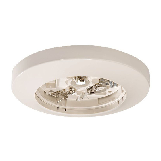
GENERAL DESCRIPTION
The Model B110LP detector base is designed for use with System Sensor models
2151 photoelectronic and 1151 ionization detector heads. This two-wire base is
equipped with screw terminals for the connection of power, ground, and an optional
remote annunciator.
MOUNTING
The detector base mounts directly to 3-½ inch and 4-inch octagon boxes and 4-inch
square boxes, with or without plaster rings. To mount the base, remove the decorative
ring by rotating it in either direction to unhook the snaps before separating the ring
from the base. Use the screws supplied with the junction box to attach the base to the
box through the appropriate slots in the base (see Figure 1). Position the decorative
ring around the base and rotate it in either direction until the ring snaps into place.
INSTALLATION GUIDELINES
Allowable loop resistance is an important specification for control panels as well as
for smoke detectors and their bases. The alarm system cannot be expected to oper-
ate correctly if system components have incompatible allowable loop resistances.
Therefore, before beginning installation, refer to the control panel manufacturer's
loop resistance specification to ensure that it is listed as compatible with the System
Sensor base and smoke detector being installed.
System Sensor smoke detectors and mounting bases are marked with a compatibility
identifier as the last digit of a five-digit code stamped on the back of the product.
Connect detectors only to compatible control units as indicated in System Sensor's
compatibility chart. This chart consists of a current list of UL-listed control unit/
detector combinations and is available from System Sensor upon request.
All wiring must be installed in compliance with the National Electrical Code and all
applicable local codes and any special requirements of the authority having jurisdic-
6.2 inches (157 mm)
0.95 inches (24 mm)
0.3 lb. (137 g)
4-inch square box with or without plaster ring. Min. depth–1.5 inches
3-1/2-inch octagon box. Min. depth–1.5 inches
0° to 49°C (32° to 120°F)
10% to 93% Relative Humidity, Noncondensing
12/24 VDC
4 Volts peak-to-peak
0.02 µF Maximum
8.5 VDC Minimum
35 VDC Maximum
120 µA Maximum
4.2 VDC Minimum at 10 mA
6.6 VDC Maximum at 100 mA
(Alarm current must be limited to 100 mA (130 mA for models 1151 and 2151) by the control panel. If it is used, the RA400Z
Remote Annunciator operates within the specified detector alarm currents.)
2.5 VDC Minimum
0.3 Seconds Minimum
34.0 Seconds Maximum
3825 Ohio Avenue, St. Charles, Illinois 60174
FIGURE 1. MOUNTING BASE TO BOX:
SHORTING
SPRING
1
1-800-SENSOR2, FAX: 630-377-6495
www.systemsensor.com
SNAP ON
DECORATIVE
RING
SCREWS
(NOT SUPPLIED)
DETECTOR
BASE
BOX
(NOT SUPPLIED)
C0503-00
I56-0594-005R
04-21
Advertisement
Table of Contents

Related Manuals for System Sensor B110LP


Summary of Contents for System Sensor B110LP
- Page 1 NFPA 72 requirements. The detector used with this base should be cleaned at least once a year. GENERAL DESCRIPTION The Model B110LP detector base is designed for use with System Sensor models SCREWS 2151 photoelectronic and 1151 ionization detector heads. This two-wire base is...
- Page 2 C0130-00 THREE-YEAR LIMITED WARRANTY System Sensor warrants its enclosed smoke detector base to be free from defects in ma- 12220 Rojas Drive, Suite 700, El Paso TX 79936 USA. Please include a note describing the terials and workmanship under normal use and service for a period of three years from malfunction and suspected cause of failure.
Need help?
Do you have a question about the B110LP and is the answer not in the manual?
Questions and answers