Table of Contents
Advertisement
Quick Links
INSTALLATION AND MAINTENANCE INSTRUCTIONS
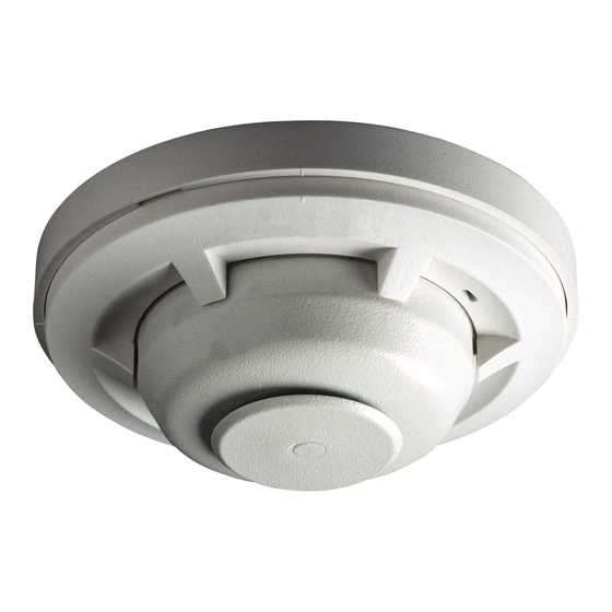
5600 Series
Mechanical Heat Detector
Single Circuit: 5601P, 5602, 5603, 5604
Dual Circuit: 5621, 5622, 5623, 5624
Before Installing
This detector must be installed in compliance with
the control panel installation manual and meet the
requirements of NFPA 72, and/or the local authority
having jurisdiction.
Read this manual carefully before using the detec-
tor. This manual should be left with the owner/user
of this equipment.
General Description
The 5600 series mechanical heat detector is in-
tended for use in property protection applications,
or for non-life-safety installations where smoke de-
tection is not practical or appropriate.
For life-safety installations, smoke detectors must
be used, in lieu of, or in addition to mechanical
heat detectors.
The 5600 series consists of both single- and dual-cir-
cuit heat detectors featuring fixed temperature thermal
sensors or combination fixed temperature/rate-of-rise
sensors, with temperature ratings of 135ºF (57ºC) or
194ºF (90ºC).
Markings on the exterior of the detector indicate the
specific activation method and temperature rating. All
models are identified as either 135ºF/57ºC or 194ºF/
90ºC. Models equipped with combination fixed tem-
perature/rate-of-rise sensors are marked FX/ROR.
Fixed temperature only models are marked FX.
Table 1. 5600 Series Mechanical Heat Detectors
Model
Circuit
No.
5601P
Single
5602
Single
5603
Single
5604
Single
5621
Dual
5622
Dual
5623
Dual
5624
Dual
NOTE: Refer to NFPA72 guidelines for spacing reductions when ceiling heights exceed 10 feet.
D500-46-00
WARNING
Temperature
Rating
135ºF (57ºC)
Fixed Temperature/Rate of Rise
194ºF (90ºC)
Fixed Temperature/Rate of Rise
135ºF (57ºC)
194ºF (90ºC)
135ºF (57ºC)
Fixed Temperature/Rate of Rise
194ºF (90ºC)
Fixed Temperature/Rate of Rise
135ºF (57ºC)
194ºF (90ºC)
Non-Resettable Fixed Temperature Sensor
The fixed temperature element reacts to heat by re-
sponding to a specific temperature setting (135ºF
or 194ºF). The detection method is based on the
spring action of a metal contact, held to the metal
chamber by a fusible alloy. When the temperature
reaches the alloy's melting point, the metal contact
will depress the diaphragm, causing the electrical
contact to close the circuit. The circular external
heat collector is released from the detector to visu-
ally indicate that the detector has been activated.
NOTE: 5600 series Fixed Temperature models (5603,
5604, 5623, and 5624) are non-resettable, and can-
not be tested.
Self-Restoring Rate-of-Rise (ROR) Sensor
The rate-of-rise element responds to a rapid rise of
temperature, approximately 15ºF (8.3ºC) per min-
ute. As the temperature rises, the air within the
sealed chamber expands. Should the chamber air
expand faster than it can escape through the cali-
brated vent, the diaphragm is depressed, and the
electrical contact closes the circuit.
NOTE: Only the ROR element of 5600 series com-
bination fixed temperature/ROR models (5601P,
5602, 5621, and 5622) are self-restoring, and may be
tested using a hair dryer or heat gun. When testing
the ROR element, to prevent the activation of the
fixed temperature element, the heat source must not
exceed the fixed temperature rating of the detector.
Thermal Sensor
Fixed Temperature
Fixed Temperature
Fixed Temperature
Fixed Temperature
1
3825 Ohio Avenue, St. Charles, Illinois 60174
1-800-SENSOR2, FAX: 630-377-6495
www.systemsensor.com
UL Maximum Spacing
(10-foot ceiling)
50-feet x 50-feet
50-feet x 50-feet
25-feet x 25-feet
25-feet x 25-feet
50-feet x 50-feet
50-feet x 50-feet
25-feet x 25-feet
25-feet x 25-feet
I56-2175-002R
Advertisement
Table of Contents

Related Manuals for System Sensor 5600 Series


Summary of Contents for System Sensor 5600 Series
- Page 1 Markings on the exterior of the detector indicate the the ROR element, to prevent the activation of the specific activation method and temperature rating. All fixed temperature element, the heat source must not models are identified as either 135ºF/57ºC or 194ºF/ exceed the fixed temperature rating of the detector. 90ºC. Models equipped with combination fixed tem- perature/rate-of-rise sensors are marked FX/ROR. Fixed temperature only models are marked FX. Table 1. 5600 Series Mechanical Heat Detectors UL Maximum Spacing Model Temperature Circuit Thermal Sensor Rating (10-foot ceiling) 5601P Single 135ºF (57ºC)
- Page 2 Mounting Bracket Figure 2. Reversible Mounting Bracket: All 5600 series detectors are equipped with a mounting bracket that includes mounting slots to accommodate single-gang, 3 ⁄ ˝ octagonal, and Surface–mount 4˝ octagonal electrical boxes, as well as 4˝ square boxes equipped with a plaster ring (Figure 1). The mounting bracket is reversible to accommodate flush-mount and surface–mount installations (Fig- ure 2).
- Page 3 Figure 4. Wiring Diagram – Dual Circuit Models: Control Panel Auxiliary Auxiliary Device Device – Auxiliary Auxiliary Device Device Installation Only the ROR element of 5600 series combination Remove power from the alarm control unit or initi- fixed temperature/ROR models (5601P, 5602, 5621, ating device circuits before installing detectors. and 5622) are self-restoring, and may be tested us- 1. Detach the detector from the mounting bracket by ing a hair dryer or heat gun. rotating the detector 1⁄4 turn counter-clockwise. 2. Orient the mounting bracket properly for either a WARNING flush- or surface-mount installation (Figure 2). 3. Select the pair of mounting holes suitable for the When testing the ROR element, to prevent the ac- junction box, (figure 1) and secure the bracket to...
- Page 4 Specifications: Operating Voltage/Contact Ratings (Resistive): 6 – 125 VAC / 3A 6 – 28 VDC / 1A 125 VDC / 0.3A 250 VDC / 0.1A Maximum Installation Temperature: Models 5601P, 5603, 5621, and 5623: 100°F (38°C) Models 5602, 5604, 5622, and 5624: 150°F (65.6°C) Alarm Temperature: Models 5601P, 5603, 5621, and 5623: 135°F (57°C) Models 5602, 5604, 5622, and 5624: 194°F (90°C) Rate-of-Rise Threshold: 15°F (8.3°C) per minute (models 5601P, 5602, 5621, and 5622 only) Operating Humidity Range: 5 to 95% RH non-condensing Input Terminals: 14 – 22 AWG Back Box Mounting: ⁄ ″ octagonal 4″ octagonal Single gang 4″ square with a square to round plaster ring Dimensions with mounting bracket: Diameter: 4.57 inches (11.6cm) Height: 1.69 inches (4.3cm) Weight: 6 oz. (170 grams) CAUTION To prevent the activation of the fixed temperature element, the shipping and storage temperature must not exceed 122°F (50°C). Please refer to insert for the Limitations of Fire Alarm Systems Three-Year Limited Warranty System Sensor warrants its enclosed product to be Department, RA #__________, 3825 Ohio Avenue, St.
Need help?
Do you have a question about the 5600 Series and is the answer not in the manual?
Questions and answers
5603 is beeping intermitent. is there a battery???
The context does not mention a battery for the System Sensor 5603. Therefore, it cannot be determined if the 5603 has a battery related to the intermittent beeping issue.
This answer is automatically generated